Toyota Tacoma (2015-2018) Service Manual: Components
COMPONENTS
ILLUSTRATION
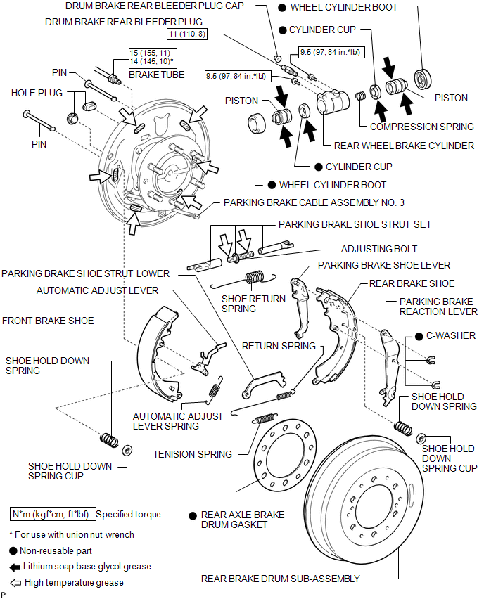
 Rear Brake
...
 Disassembly
DISASSEMBLY
PROCEDURE
1. REMOVE FRONT BRAKE SHOE
(a) Using SST, remove the shoe return spring from the front brake shoe.
SST: 09921-00010
(b) Using needle-nose pliers, remove the ret ...
Other materials:
Transfer L4 Position Switch Circuit (C1268)
DESCRIPTION
DTC No.
Detection Item
DTC Detection Condition
Trouble Area
C1268
Transfer L4 Position Switch Circuit
Either of the following is detected:
The skid control ECU (brake actuator assembly) dete ...
Vehicle Lift And Support Locations
VEHICLE LIFT AND SUPPORT LOCATIONS
1. NOTICE ABOUT VEHICLE CONDITION WHEN JACKING UP VEHICLE
(a) The vehicle must be unloaded before jacking up / lifting up the vehicle.
Never jack up / lift up a heavily loaded vehicle.
(b) When removing heavy parts such as the engine and transmission, the cent ...
Installation
INSTALLATION
PROCEDURE
1. INSTALL FRONT BUMPER ASSEMBLY
(a) w/ Fog Light:
(1) Connect the 2 connectors.
(b) Engage the 3 claws and guide to install the front bumper assembly.
(c) Remove the protective tape.
(d) Install the 6 clips.
(e) Engage the clamp.
(f) Connect the connector.
(g) Insta ...
