Toyota Tacoma (2015-2018) Service Manual: Installation
INSTALLATION
PROCEDURE
1. INSTALL REAR BUMPER ASSEMBLY
(a) Using an engine lifter or equivalent, engage the 2 pins to install the rear bumper assembly as shown in the illustration.
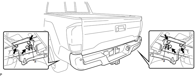 Text in Illustration
|
*a |
Pin |
- |
- |
NOTICE:
- Using plate lift attachments or equivalent, set the rear bumper assembly on a flat surface.
- Be sure to perform the operation with 2 persons or more.
- Be careful not to damage the rear bumper assembly.
(b) Install the 6 bolts.
Torque:
90 N·m {918 kgf·cm, 66 ft·lbf}
(c) Connect the 3 connectors.
2. INSTALL NO. 1 RECEIVER HITCH ATTACHMENT REINFORCEMENT
(a) Engage the 4 guides and install the 2 No. 1 receiver hitch attachment reinforcements with the 8 bolts.
Torque:
90 N·m {918 kgf·cm, 66 ft·lbf}
3. PERFORM BLIND SPOT MONITOR BEAM AXIS INSPECTION (w/ Blind Spot Monitor)
Click here .gif)
4. PERFORM DIAGNOSTIC SYSTEM CHECK (w/ Blind Spot Monitor)
Click here
 Reassembly
REASSEMBLY
PROCEDURE
1. INSTALL REAR BUMPER SIDE STAY LH
(a) Install the rear bumper side stay LH with the 2 bolts.
Torque:
30 N·m {306 kgf·cm, 22 ft·lbf}
...

Other materials:
Operation Check
OPERATION CHECK
1. BLIND SPOT MONITOR BEAM AXIS INSPECTION
(a) Procedure to enter Test Mode
(1) Connect the Techstream to the DLC3.
(2) Turn the ignition switch to ON.
(3) Turn the blind spot monitor main switch assembly (warning canceling switch
assembly) on.
(4) Turn the Techstream on.
(5 ...
HD Radio Tuner Malfunction (B1551,B158D,B15A0,B15B0,B15B3,B15B4,B15B7)
DESCRIPTION
These DTCs are stored when a malfunction occurs in the radio and display receiver
assembly.
DTC No.
DTC Detection Condition
Trouble Area
B1551
When one of the conditions below is met:
"HD Radio" tune ...
Diagnosis System
DIAGNOSIS SYSTEM
1. DESCRIPTION
The 4 wheel drive control ECU records DTCs when the ECU detects a malfunction
in the ECU itself or in system circuits.
The DTCs can be read through the DLC3 of the vehicle. When the system seems to
be malfunctioning, use the Techstream to check for malfunctions ...
