COMPONENTS
ILLUSTRATION
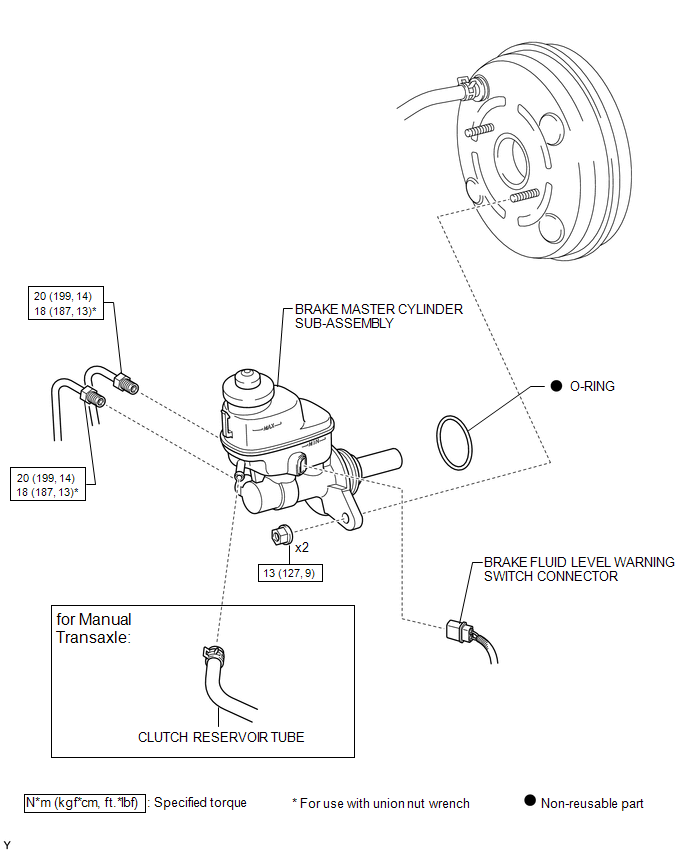
ILLUSTRATION
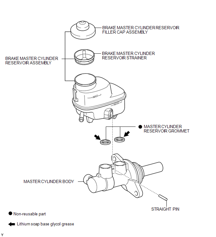
Related Tacoma materials
Rear Cross Traffic Alert Buzzer
Components
COMPONENTS
ILLUSTRATION
Installation
INSTALLATION
PROCEDURE
1. INSTALL REAR CROSS TRAFFIC ALERT BUZZER
(a) Engage the clamp to install the rear cross traffic alert buzzer.
(b) Connect the connector.
2. INSTALL ...
Dtc Check / Clear
DTC CHECK / CLEAR
1. DTC CHECK / CLEAR (when Using Techstream)
(a) Check for DTCs.
(1) Connect the Techstream to the DLC3.
(2) Turn the ignition switch to ON.
(3) Turn the Techstream on.
(4) Enter the following menus: Chassis / ABS/VSC/ TRAC / Trouble Codes.
(5) Read the DTCs by following the ...
Ignition Coil And Spark Plug
Components
COMPONENTS
ILLUSTRATION
Installation
INSTALLATION
PROCEDURE
1. INSTALL SPARK PLUG
HINT:
Perform "Inspection After Repairs" after replacing the spark plug (See page
...