Toyota Tacoma (2015-2018) Service Manual: System Description
SYSTEM DESCRIPTION
1. GENERAL
(a) This system uses ultrasonic sensors to detect any obstacles at the corners and the rear of the vehicle. The system then informs the driver of the distance between the sensors and an obstacle as well as their positions by indicating them on the multi-information display (in the combination meter assembly) and by sounding a buzzer.
2. FUNCTION OF COMPONENTS
|
Component |
Function |
|---|---|
|
No. 1 Ultrasonic Sensor |
Detects the distance between the vehicle and an obstacle |
|
No. 1 Clearance Warning Buzzer |
Sounds to inform the driver according to the distance to an obstacle |
|
Multi-information Display (on Combination Meter Assembly) |
|
|
Combination Meter Assembly |
Transmits the vehicle speed signal to the clearance warning ECU assembly |
|
Back Sonar or Clearance Sonar Switch Assembly |
Operating this switch enables, disables or cuts off the operation of the intuitive parking assist system |
|
Clearance Warning ECU Assembly |
|
|
Main Body ECU (Multiplex Network Body ECU) |
Transmits the destination information to the clearance warning ECU assembly |
|
ECM |
Transmits the shift position signal to the clearance warning ECU assembly |
|
Air Conditioning Amplifier Assembly |
Transmits the temperature information signal to the clearance warning ECU assembly |
3. OPERATION EXPLANATION
(a) The operating conditions of each ultrasonic sensor differ according to the installation position as shown in the table below.
|
Installation Position |
Operating Condition |
|---|---|
|
Rear Corner Sensor |
|
|
Rear Center Sensor |
When the system operates, the clearance warning ECU assembly transmits ultrasonic waves from the ultrasonic sensors. If these waves encounter an obstacle within one or more of the sensors ranges, the waves are reflected back to the sensors, which transmit them to the clearance warning ECU assembly.
Based on this information, the clearance warning ECU assembly sends signals to the multi-information display and the clearance warning buzzer. The approximate distance between the vehicle and the obstacle is then indicated, and the buzzer sounds.
HINT:
Refer to Detection Range Measurement and Display Inspection (See page
.gif) ).
).
4. COMMUNICATION SIGNALS OF COMPONENTS
HINT:
- Allocation refers to the process of the clearance warning ECU assembly setting aside IDs for the sensors.
- The vehicle has the sensors arranged in 2 groups. There is a front series and a rear series. The sensors are connected in a "daisy chain".
(a) Initialization mode:
An ID is allocated to each sensor and sensor diagnosis is performed.
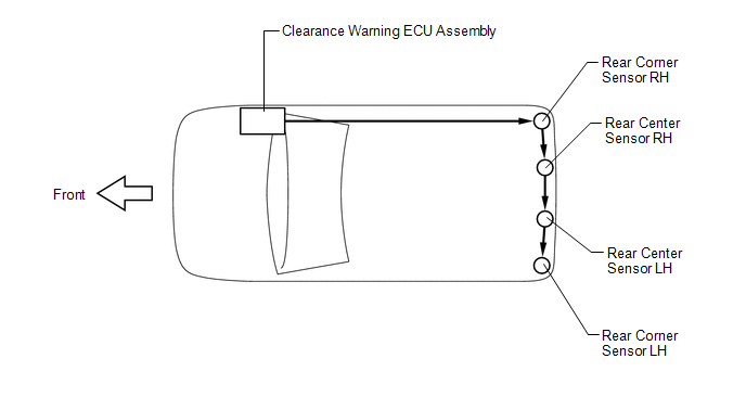
(1) When the initial check is operating (the ignition switch ON and the back sonar or clearance sonar switch assembly on), the clearance warning ECU assembly provides power to the first sensors in each series (rear corner sensor RH).
(2) After the power is supplied, the rear corner sensor RH enter standby mode to receive an ID from the ECU. When a certain amount of time has elapsed, the ECU sends an ID allocation signal to these sensors.
(3) The rear corner sensor RH receive the ID allocation signal from the ECU and perform self-diagnosis. When the sensor self-diagnosis is completed, the ECU sends an ID allocation confirmation signal to these sensors.
(4) After the ID allocation confirmation is performed, the ECU provides power to the second sensors in each series (rear center sensor RH) via the first sensors. In the same manner as the first sensors, the second sensors enter standby mode. When a certain amount of time has elapsed, the ECU sends an ID allocation signal to the second sensors.
(5) The above operation will be repeated until an ID is allocated to the last sensor, which is in the rear series (rear corner sensor LH). Initialization ends when ID allocation to all ultrasonic sensors is completed.
(b) Detection mode:
After initialization mode is completed, the system switches into detection mode. In detection mode, the clearance warning ECU assembly sends information request signals and sensor activation signals to the ultrasonic sensors and receives detection result signals from the sensors.
(1) The ECU regularly sends ID signals, information request signals, and sensor activation signals to each ultrasonic sensor according to the communication schedule.
(2) When a certain amount of time has elapsed (sensor detection operation is completed), the ECU sends an ID signal to the sensor to receive a detection result signal.
(3) The ultrasonic sensor sends a detection result signal or detection information signal to the ECU.
(4) The above operation is performed repeatedly for each ultrasonic sensor.
 How To Proceed With Troubleshooting
CAUTION / NOTICE / HINT
HINT:
Use the following procedure to troubleshoot the intuitive parking assist
system.
*: Use the Techstream.
PROCEDURE
1.
VEHI ...
 Operation Check
OPERATION CHECK
1. MALFUNCTION DISPLAY (MULTI-INFORMATION DISPLAY)
(a) Open circuit indication
(1) If there is an open circuit between a No. 1 ultrasonic sensor and the clearance
warning ECU asse ...
Other materials:
Clearance Warning Ecu
Components
COMPONENTS
ILLUSTRATION
Installation
INSTALLATION
PROCEDURE
1. INSTALL CLEARANCE WARNING ECU ASSEMBLY
(a) Connect the connector.
(b) Engage the 2 guides to install the clearance warning ECU assembly.
(c) Install the 2 screws.
2. INSTALL AIR CONDITIONING CONTROL ASSEMBLY (f ...
Data List / Active Test
DATA LIST / ACTIVE TEST
1. DATA LIST
HINT:
Using the Techstream to read the Data List allows the values or states of switches,
sensors, actuators and other items to be read without removing any parts. This non-intrusive
inspection can be very useful because intermittent conditions or signals ...
Removal
REMOVAL
PROCEDURE
1. REMOVE REAR SEAT CUSHION ASSEMBLY
(a) Remove the 2 bolts and rear seat cushion assembly.
2. REMOVE REAR SEATBACK HINGE COVER
(a) Disengage the 6 claws to remove the 2 rear seatback hinge covers.
...
