Toyota Tacoma (2015-2018) Service Manual: Diagnosis System
DIAGNOSIS SYSTEM
1. CHECK DLC3
(a) Check the DLC3 (See page .gif) ).
).
2. INSPECT BATTERY VOLTAGE
(a) Measure the battery voltage.
Standard Voltage:
11 to 14 V
If the voltage is below 11 V, recharge or replace the battery.
3. SELF-DIAGNOSTIC MODE (OPERATING IGNITION KEY CYLINDER)
(a) Switch to self-diagnostic mode.
(1) Insert the key into the ignition key cylinder and remove it.
(2) Within 5 seconds after the key is removed, insert it into the ignition key cylinder and then turn the ignition switch to ON then off once. (End in off)
(3) Within 30 seconds after turning the ignition switch off, perform the following 9 times: Turn the ignition switch to ON then off. (End in off)
HINT:
Turning the ignition switch to ON after the procedure above has been completed will end the self-diagnostic mode.
NOTICE:
If the system fails to enter self-diagnostic mode, the system will return to normal mode.
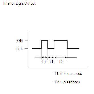
(b) Check that the system has switched to self-diagnostic mode by checking the interior light output pattern.
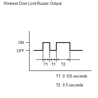
(c) Check that the system has switched to self-diagnostic mode by checking the wireless door lock buzzer output pattern.
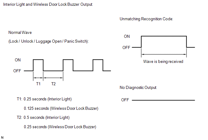
(d) Check the diagnostic outputs when the door control transmitter module set sub-assembly switch is held down. The diagnostic outputs can be checked by the interior light and wireless door lock buzzer patterns.
 Registration
REGISTRATION
CAUTION / NOTICE / HINT
HINT:
Register a new recognition code when replacing the door control transmitter
module set sub-assembly or the door control receiver.
Add mode ...
 Terminals Of Ecu
TERMINALS OF ECU
1. CHECK DRIVER SIDE JUNCTION BLOCK AND MAIN BODY ECU (MULTIPLEX NETWORK BODY
ECU)
(a) Disconnect the MB main body ECU (multiplex network body ECU) connectors.
(b) Measure the ...
Other materials:
How To Proceed With Troubleshooting
CAUTION / NOTICE / HINT
HINT:
The vehicle stability control system troubleshooting procedures are
based on the premise that the CAN communication system is functioning normally.
Check the CAN communication system first before troubleshooting the vehicle
stability control system ...
Driver Side Seat Belt Warning Light does not Operate
DESCRIPTION
When the ignition switch is ON, the airbag sensor assembly transmits front seat
inner belt status signals to the combination meter assembly through CAN. If the
driver seat belt is not fastened, the combination meter assembly blinks the driver
side seat belt warning light. If the s ...
Front Passenger Side Power Window Auto Up / Down Function does not Operate with
Front Passenger Side Power Window Switch
DESCRIPTION
If the manual up/down function can be performed but the auto up/down function
cannot, the fail-safe mode may be functioning.
If the power window initialization (See page
) has not been performed, the auto up/down function will not operate.
WIRING DIAGRAM
CAUTION / NOTICE / HIN ...
