Toyota Tacoma (2015-2018) Service Manual: Terminals Of Ecu
TERMINALS OF ECU
1. CHECK ENGINE SWITCH

(a) Measure the resistance and voltage according to the value(s) in the table below.
|
Terminal No. (Symbol) |
Input/Output |
Wiring Color |
Terminal Description |
Condition |
Specified Condition |
Related Data List Item/DTC |
|---|---|---|---|---|---|---|
|
E28-6 (AGND) - Body ground |
- |
Y - Body ground |
Transponder key amplifier ground |
Always |
Below 1 Ω |
- |
|
E28-7 (TXCT) - E28-6 (AGND) |
Input |
R - Y |
Immobiliser communication input |
Engine switch off, brake pedal not depressed, 30 seconds or more elapsed after driver door opened and then closed |
Below 1 V |
- |
|
E28-8 (CODE) - E28-6 (AGND) |
Output |
SB - Y |
Immobiliser communication output |
Engine switch off, brake pedal not depressed, 30 seconds or more elapsed after driver door opened and then closed |
Below 1 V |
- |
|
E28-10 (VC5) - E28-6 (AGND) |
Input |
W - Y |
Transponder key amplifier power supply |
Engine switch off, brake pedal not depressed, 30 seconds or more elapsed after driver door opened and then closed |
Below 1 V |
- |
(b) Check for pulses according to the value(s) in the table below.
|
Terminal No. (Symbol) |
Input/Output |
Wiring Color |
Terminal Description |
Condition |
Specified Condition |
Related Data List Item/DTC |
|---|---|---|---|---|---|---|
|
E28-7 (TXCT) - E28-6 (AGND) |
Input |
R - Y |
Signal input from certification ECU (smart key ECU assembly) (Code sent from certification ECU (smart key ECU assembly) to transponder key amplifier built into engine switch, and then transmitted by transponder key amplifier antenna as radio waves) |
Engine switch off, key not in cabin, within 30 seconds after engine switch pressed |
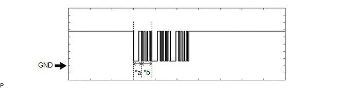
Pulse generation (See waveform 1) |
|
|
E28-8 (CODE) - E28-6 (AGND) |
Output |
SB - Y |
Signal output to certification ECU (smart key ECU assembly) (Radio waves from transponder key amplifier built into engine switch used to detect key information. Key information then sent to certification ECU (smart key ECU assembly)) |
Engine switch off, engine switch pressed with key held near engine switch* |
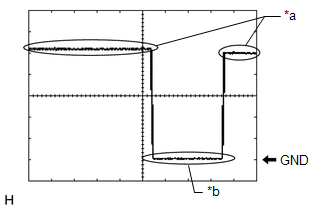
Pulse generation (See waveform 2) |
|
|
E28-10 (VC5) - E28-6 (AGND) |
Input |
W - Y |
Transponder key amplifier power supply (Power supplied from certification ECU (smart key ECU assembly) when transponder key amplifier built into engine switch activated) |
Engine switch off, key not in cabin, within 30 seconds after engine switch pressed |
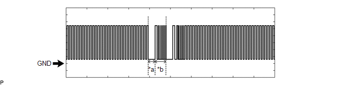
Pulse generation (See waveform 3) |
If the result is not as specified, the engine switch may be malfunctioning.
HINT:
*: Remove the key battery before performing this inspection.
(c) Inspect using an oscilloscope.
NOTICE:
The waveform shown in the illustration is an example for reference only. Noise, chattering, etc. are not shown.
(1) Waveform 1 (Reference)
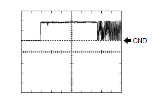 Measurement Condition
|
Item |
Content |
|---|---|
|
Tester Connection |
E28-7 (TXCT) - E28-6 (AGND) |
|
Tool Setting |
2 V/DIV., 20 ms./DIV. |
|
Condition |
Engine switch off, key not in cabin, within 30 seconds after engine switch pressed |
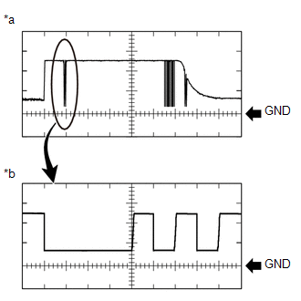
(2) Waveform 2 (Reference)
 Text in Illustration
|
*a |
Waveform |
|
*b |
Waveform (detail) |
|
Item |
Content |
|---|---|
|
Tester Connection |
E28-8 (CODE) - E28-6 (AGND) |
|
Tool Setting |
|
|
Condition |
Engine switch off, engine switch pressed with key held near engine switch* |
HINT:
*: Remove the key battery before performing this inspection.
(3) Waveform 3 (Reference)
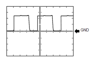 Measurement Condition
|
Item |
Content |
|---|---|
|
Tester Connection |
E28-10 (VC5) - E28-6 (AGND) |
|
Tool Setting |
2 V/DIV., 200 ms./DIV. |
|
Condition |
Engine switch off, key not in cabin, within 30 seconds after engine switch pressed |
2. CHECK CERTIFICATION ECU (SMART KEY ECU ASSEMBLY)
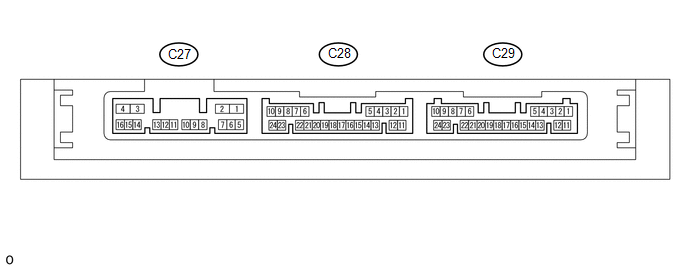
(a) Disconnect the C27 and C29 certification ECU (smart key ECU assembly) connectors.
(b) Measure the resistance and voltage according to the value(s) in the table below.
|
Terminal No. (Symbol) |
Input/Output |
Wiring Color |
Terminal Description |
Condition |
Specified Condition |
Related Data List Item/DTC |
|---|---|---|---|---|---|---|
|
C29-10 (+B) - C29-11 (E) |
Input |
P - W-B |
+B power supply |
Always |
11 to 14 V |
- |
|
C27-4 (CUTB) - C29-11 (E) |
Input |
GR - W-B |
Dark current cut pin |
Always |
11 to 14 V |
- |
|
C29-11 (E) - Body ground |
- |
W-B - Body ground |
Ground |
Always |
Below 1 Ω |
- |
(c) Reconnect the C27 and C29 certification ECU (smart key ECU assembly) connectors.
(d) Measure the resistance and voltage according to the value(s) in the table below.
|
Terminal No. (Symbol) |
Input/Output |
Wiring Color |
Terminal Description |
Condition |
Specified Condition |
Related Data List Item/DTC |
|---|---|---|---|---|---|---|
|
C27-3 (IG1D) - C29-11 (E) |
Input |
B - W-B |
Ignition power supply |
Engine switch off → on (IG) |
Below 1 V → 11 to 14 V |
Ignition Switch |
|
C29-19 (IND) - C29-11 (E) |
Output |
V - W-B |
Security indicator output |
Engine switch off → on (IG) |
Pulse generation → Below 2 V |
- |
|
C29-14 (TXCT) - C29-12 (AGND) |
Output |
R - Y |
Signal output to transponder key amplifier |
Engine switch off, brake pedal not depressed, 30 seconds or more elapsed after driver door opened and then closed |
Below 1 V |
|
|
C29-13 (CODE) - C29-12 (AGND) |
Input |
SB - Y |
Signal input from transponder key amplifier |
Engine switch off, brake pedal not depressed, 30 seconds or more elapsed after driver door opened and then closed |
Below 1 V |
|
|
C29-15 (VC5) - C29-12 (AGND) |
Output |
W - Y |
Transponder key amplifier power supply |
Engine switch off, brake pedal not depressed, 30 seconds or more elapsed after driver door opened and then closed |
Below 1 V |
|
|
C29-12 (AGND) - Body ground |
- |
Y - Body ground |
Transponder key amplifier ground |
Always |
Below 1 Ω |
|
|
C27-7 (EFII) - C29-11 (E) |
Input |
Y - W-B |
EFI communication input (Signal input from ECM to certification ECU (smart key ECU assembly)) |
Engine switch off |
11 to 14 V |
|
|
C27-6 (EFIO) - C29-11 (E) |
Output |
SB - W-B |
EFI communication output (Signal output from certification ECU (smart key ECU assembly) to ECM) |
Engine switch off |
11 to 14 V |
(e) Check for pulses according to the value(s) in the table below.
|
Terminal No. (Symbol) |
Input/Output |
Wiring Color |
Terminal Description |
Condition |
Specified Condition |
Related Data List Item/DTC |
|---|---|---|---|---|---|---|
|
C29-14 (TXCT) - C29-12 (AGND) |
Output |
R - Y |
Signal output to transponder key amplifier (Code sent from certification ECU (smart key ECU assembly) to transponder key amplifier built into engine switch, and then transmitted by transponder key amplifier antenna as radio waves) |
Engine switch off, key not in cabin, within 30 seconds after engine switch pressed |
Pulse generation (See waveform 1) |
|
|
C29-13 (CODE) - C29-12 (AGND) |
Input |
SB - Y |
Signal input from transponder key amplifier (Radio waves from transponder key amplifier built into engine switch used to detect key information. Key information then sent to certification ECU (smart key ECU assembly)) |
Engine switch off, engine switch pressed with key held near engine switch* |
Pulse generation (See waveform 2) |
|
|
C29-15 (VC5) - C29-12 (AGND) |
Output |
W - Y |
Transponder key amplifier power supply (Power supplied from certification ECU (smart key ECU assembly) when transponder key amplifier built into engine switch activated) |
Engine switch off, key not in cabin, within 30 seconds after engine switch pressed |
Pulse generation (See waveform 3) |
|
|
C27-7 (EFII) - C29-11 (E) |
Input |
Y - W-B |
EFI communication input (Signal input from ECM to certification ECU (smart key ECU assembly)) |
Within 3 seconds of engine start or within 3 seconds of engine switch turned on (IG) after battery cable disconnected and reconnected |
Pulse generation (See waveform 4) |
|
|
C27-6 (EFIO) - C29-11 (E) |
Output |
SB - W-B |
EFI communication output (Signal output from certification ECU (smart key ECU assembly) to ECM) |
Engine switch on (IG) using registered electrical key transmitter sub-assembly |
Pulse generation (See waveform 5) |
If the result is not as specified, the certification ECU (smart key ECU assembly) may be malfunctioning.
HINT:
*: Remove the key battery before performing this inspection.
(f) Inspect using an oscilloscope.
NOTICE:
The waveform shown in the illustration is an example for reference only. Noise, chattering, etc. are not shown.
(1) Waveform 1 (Reference)
Measurement Condition
|
Item |
Content |
|---|---|
|
Tester Connection |
C29-14 (TXCT) - C29-12 (AGND) |
|
Tool Setting |
2 V/DIV., 20 ms./DIV. |
|
Condition |
Engine switch off, key not in cabin, within 30 seconds after engine switch pressed |
(2) Waveform 2 (Reference)
Text in Illustration
|
*a |
Waveform |
|
*b |
Waveform (detail) |
|
Item |
Content |
|---|---|
|
Tester Connection |
C29-13 (CODE) - C29-12 (AGND) |
|
Tool Setting |
|
|
Condition |
Engine switch off, engine switch pressed with key held near engine switch* |
HINT:
*: Remove the key battery before performing this inspection.
(3) Waveform 3 (Reference)
Measurement Condition
|
Item |
Content |
|---|---|
|
Tester Connection |
C29-15 (VC5) - C29-12 (AGND) |
|
Tool Setting |
2 V/DIV., 200 ms./DIV. |
|
Condition |
Engine switch off, key not in cabin, within 30 seconds after engine switch pressed |
(4) Waveform 4 (Reference)
 Text in Illustration
|
*a |
Approximately 160 ms |
*b |
Approximately 270 ms |
|
Item |
Content |
|---|---|
|
Tester Connection |
C27-7 (EFII) - C29-11 (E) |
|
Tool Setting |
2 V/DIV., 500 ms./DIV. |
|
Condition |
Within 3 seconds of engine start or within 3 seconds of engine switch turned on (IG) after battery cable disconnected and reconnected |
(5) Waveform 5 (Reference)
 Text in Illustration
|
*a |
Approximately 160 ms |
*b |
Approximately 270 ms |
|
Item |
Content |
|---|---|
|
Tester Connection |
C27-6 (EFIO) - C29-11 (E) |
|
Tool Setting |
2 V/DIV., 500 ms./DIV. |
|
Condition |
Engine switch on (IG) using registered electrical key transmitter sub-assembly |
3. CHECK STEERING LOCK ECU (STEERING LOCK ACTUATOR OR UPR BRACKET ASSEMBLY)

(a) Measure the voltage and resistance according to the value(s) in the table below.
|
Terminal No. (Symbol) |
Input/Output |
Wiring Color |
Terminal Description |
Condition |
Specified Condition |
Related Data List Item/DTC |
|---|---|---|---|---|---|---|
|
S45-1 (GND) - Body ground |
- |
W-B - Body ground |
Ground |
Always |
Below 1 Ω |
- |
|
S45-3 (IGE) - S45-1 (GND) |
Input |
Y - W-B |
Steering lock motor operation permission signal (motor operation permission signal supplied by certification ECU (smart key ECU assembly)) |
Steering lock motor operates when all conditions met, and then door opened:
|
Pulse generation (See waveform 1) |
|
|
S45-4 (SLP1) - S45-1 (GND) |
Output |
BE - W-B |
Steering lock bar position signal (signal output from steering unlock sensor) |
Steering locked → unlocked*1 |
11 to 14 V → Below 1.5 V |
|
|
S45-6 (IG2) - S45-1 (GND) |
Input |
B - W-B |
IG signal (IG2 power supply input for steering lock motor) |
Engine switch off → on (IG) |
Below 1 V → 11 to 14 V |
|
|
S45-7 (B) - Body ground |
Output |
R - Body ground |
Constant power supply |
Always |
11 to 14 V |
B2788 |
If the result is not as specified, the steering lock ECU (steering lock actuator or upr bracket assembly) may be malfunctioning.
HINT:
*1: The steering locks when any door is opened with the shift lever in P and the engine switch off. The steering unlocks when the engine switch is turned on (ACC).
(b) Inspect using an oscilloscope.
NOTICE:
The waveform shown in the illustration is an example for reference only. Noise, chattering, etc. are not shown.
(1) Waveform 1 (Reference)
 Text in Illustration
|
*a |
Steering lock motor not operating |
|
*b |
Steering lock motor operating |
|
Item |
Content |
|---|---|
|
Tester Connection |
S45-3 (IGE) - S45-1 (GND) |
|
Tool Setting |
2 V/DIV., 200 ms./DIV. |
|
Condition |
Steering lock motor operates when all conditions met, and then door opened:
|
4. CHECK ECM
HINT:
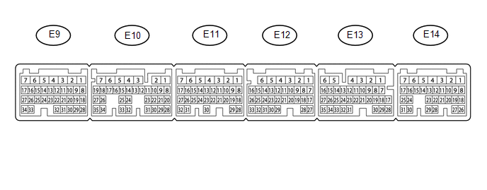
The standard voltage between each pair of ECM terminals is shown in the table below. The appropriate conditions for checking each pair of terminals are also indicated. The result of checks should be compared with the standard voltage for that pair of terminals, displayed in the "Specified Condition" column. The illustration above can be used as a reference to identify the ECM terminal locations.
|
Terminal No. (Symbol) |
Input/Output |
Wiring Color |
Terminal Description |
Condition |
Specified Condition |
Related Data List Item/DTC |
|---|---|---|---|---|---|---|
|
E11-1 (E1) - Body ground |
- |
W-B - Body ground |
Ground |
Always |
Below 1 Ω |
- |
|
E14-2 (BATT) - E11-1 (E1) |
Input |
L - W-B |
+B power supply |
Always |
11 to 14 V |
- |
|
E14-3 (+B) - E11-1 (E1) |
Input |
B - W-B |
+B power supply |
Engine switch on (IG) |
11 to 14 V |
- |
|
E14-4 (+B2) - E11-1 (E1) |
Input |
B - W-B |
+B power supply |
Engine switch on (IG) |
11 to 14 V |
- |
|
E14-9 (IMO) - E11-1 (E1) |
Input |
Y - W-B |
Certification ECU (smart key ECU assembly) communication input |
Engine switch off |
11 to 14 V |
- |
|
E14-9 (IMO) - E11-1 (E1) |
Input |
Y - W-B |
Certification ECU (smart key ECU assembly) communication input |
Within 3 seconds of engine start or within 3 seconds of engine switch turned on (IG) after battery cable disconnected and reconnected |
Pulse generation (See waveform 1) |
- |
|
E14-8 (IMI) - E11-1 (E1) |
Output |
SB - W-B |
Certification ECU (smart key ECU assembly) communication output |
Engine switch off |
11 to 14 V |
- |
|
E14-8 (IMI) - E11-1 (E1) |
Output |
SB - W-B |
Certification ECU (smart key ECU assembly) communication output |
Engine switch on (IG) using registered electrical key transmitter sub-assembly |
Pulse generation (See waveform 2) |
- |
(a) Inspect using an oscilloscope.
NOTICE:
The waveform shown in the illustration is an example for reference only. Noise, chattering, etc. are not shown.
(1) Waveform 1 (Reference)
Text in Illustration
|
*a |
Approximately 160 ms |
*b |
Approximately 270 ms |
|
Item |
Content |
|---|---|
|
Tester Connection |
E14-9 (IMO) - E11-1 (E1) |
|
Tool Setting |
2 V/DIV., 500 ms./DIV. |
|
Condition |
Within 3 seconds of engine start or within 3 seconds of engine switch turned on (IG) after battery cable disconnected and reconnected |
(2) Waveform 2 (Reference)
Text in Illustration
|
*a |
Approximately 160 ms |
*b |
Approximately 270 ms |
|
Item |
Content |
|---|---|
|
Tester Connection |
E14-8 (IMI) - E11-1 (E1) |
|
Tool Setting |
2 V/DIV., 500 ms./DIV. |
|
Condition |
Engine switch on (IG) using registered electrical key transmitter sub-assembly |
 Dtc Check / Clear
DTC CHECK / CLEAR
HINT:
When using the Techstream with the engine switch off to troubleshoot:
Connect the Techstream to the DLC3 and turn a courtesy light switch on and
off at 1.5 se ...
 Data List / Active Test
DATA LIST / ACTIVE TEST
1. DATA LIST
NOTICE:
In the table below, the values listed under "Normal Condition" are reference
values. Do not depend solely on these reference values when dec ...
Other materials:
Fail-safe Chart
FAIL-SAFE CHART
1. Fail-safe
This function minimizes the loss of operation when any abnormality occurs in
a sensor or solenoid.
Fail-safe Control List
Malfunction Part
Function
Transmission revolution sensor (NT)
During a transmission revolutio ...
Installation
INSTALLATION
PROCEDURE
1. INSTALL FRONT AXLE HUB
2. INSTALL FRONT SUSPENSION UPPER ARM
(a) Install a new nut and clip.
Torque:
110 N·m {1122 kgf·cm, 81 ft·lbf}
3. INSTALL FRONT SUSPENSION LOWER ARM
(a) Install the front suspension lower arm with the 2 bolts.
Torque:
160 N·m {1631 ...
Removal
REMOVAL
PROCEDURE
1. PRECAUTION
CAUTION:
Be sure to read Precaution thoroughly before servicing (See page
).
NOTICE:
After turning the ignition switch off, waiting time may be required before disconnecting
the cable from the negative (-) battery terminal. Therefore, make sure to read the
...
