Toyota Tacoma (2015-2018) Service Manual: Data Signal Circuit between Radio Receiver and Stereo Jack Adapter
DESCRIPTION
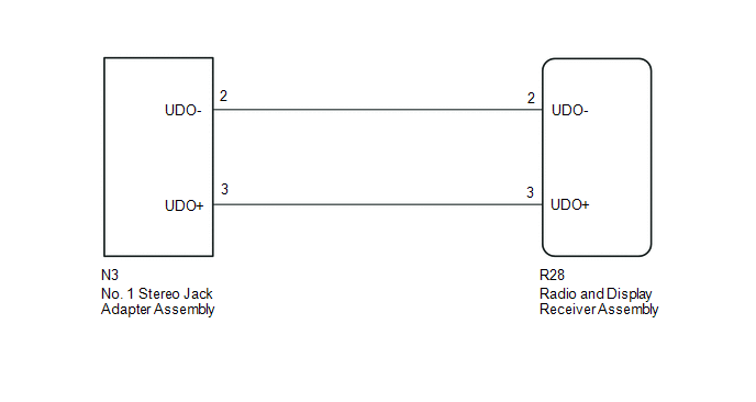
The No. 1 stereo jack adapter assembly sends the sound data signal or image data signal from a USB device to the radio and display receiver assembly via this circuit.
WIRING DIAGRAM
PROCEDURE
|
1. |
CHECK HARNESS AND CONNECTOR (RADIO AND DISPLAY RECEIVER ASSEMBLY - NO. 1 STEREO JACK ADAPTER ASSEMBLY) |
(a) Disconnect the R28 radio and display receiver assembly connector.
(b) Disconnect the N3 No. 1 stereo jack adapter assembly connector.
(c) Measure the resistance according to the value(s) in the table below.
Standard Resistance:
|
Tester Connection |
Condition |
Specified Condition |
|---|---|---|
|
N3-2 (UDO-) - R28-2 (UDO-) |
Always |
Below 1 Ω |
|
N3-3 (UDO+) - R28-3 (UDO+) |
Always |
Below 1 Ω |
|
N3-2 (UDO-) - Body ground |
Always |
10 kΩ or higher |
|
N3-3 (UDO+) - Body ground |
Always |
10 kΩ or higher |
| OK | .gif) |
PROCEED TO NEXT SUSPECTED AREA SHOWN IN PROBLEM SYMPTOMS TABLE |
| NG | |
REPAIR OR REPLACE HARNESS OR CONNECTOR |
 Sound Signal Circuit between Radio Receiver and Stereo Jack Adapter
DESCRIPTION
The No. 1 stereo jack adapter assembly sends the sound signal from an external
device to the radio and display receiver assembly via this circuit.
If there is an open or short in the c ...
 Data Signal Circuit between Radio Receiver and Extension Module
DESCRIPTION
The stereo component tuner assembly sends the image data signal to the radio
and display receiver assembly via this circuit.
WIRING DIAGRAM
PROCEDURE
1.
CHEC ...
Other materials:
Pressure Control Solenoid "D" Electrical (Shift Solenoid Valve SLT) (P2716)
DESCRIPTION
Refer to the system description for DTC P2714 (See page
).
DTC No.
DTC Detection Condition
Trouble Area
P2716
Open or short is detected in shift solenoid valve SLT circuit for 1 second
or more while driving (1 trip dete ...
Luggage compartment features
Behind the rear seat (Double
Cab models only)
1.Cargo net hooks (vehicles with sub woofer)
2.Grocery bag hooks
3.Flashlight holder
4.Storage boxes
Deck
1. Auxiliary boxes
2. Tie-down cleats
3. Deck hooks
Auxiliary boxes
Left side
1. Turn the knob counterclockwise.
2. Open the ...
Brake System (P157800)
DESCRIPTION
This DTC is stored when a malfunction is detected in the vehicle stability control
system.
DTC No.
Detection Item
DTC Detection Condition
Trouble Area
MIL
P157800
Brake System
While the igni ...
