Toyota Tacoma (2015-2018) Service Manual: Data Signal Circuit between Radio Receiver and Extension Module
DESCRIPTION
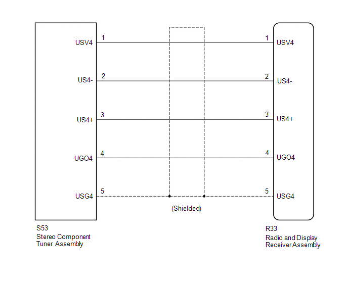
The stereo component tuner assembly sends the image data signal to the radio and display receiver assembly via this circuit.
WIRING DIAGRAM
PROCEDURE
|
1. |
CHECK NO. 1 NAVIGATION WIRE |
(a) Disconnect the R33 radio and display receiver assembly connector.
(b) Disconnect the S53 stereo component tuner assembly connector.
|
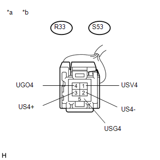
(c) Measure the resistance according to the value(s) in the table below. Standard Resistance:
|
|
| OK | .gif) |
PROCEED TO NEXT SUSPECTED AREA SHOWN IN PROBLEM SYMPTOMS TABLE |
| NG | |
REPLACE NO. 1 NAVIGATION WIRE |
 Data Signal Circuit between Radio Receiver and Stereo Jack Adapter
DESCRIPTION
The No. 1 stereo jack adapter assembly sends the sound data signal or image data
signal from a USB device to the radio and display receiver assembly via this circuit.
WIRING DIAGRAM
...
 Microphone Circuit between Microphone and Radio Receiver
DESCRIPTION
The radio and display receiver assembly and telephone microphone assembly are
connected to each other using the microphone connection detection signal lines.
Using this circuit, the ra ...
Other materials:
Installation
INSTALLATION
CAUTION / NOTICE / HINT
CAUTION:
Wear protective gloves. Sharp areas on the parts may injure your hands.
HINT:
Use the same procedure for both the RH and LH sides.
The procedure described below is for the LH side.
PROCEDURE
1. INSTALL FRONT SEAT AIRBAG ASSEMBLY ...
Components
COMPONENTS
ILLUSTRATION
*1
CHARCOAL CANISTER ASSEMBLY
*2
CHARCOAL CANISTER FUEL HOSE
*3
CHARCOAL CANISTER LEAK DETECTION PUMP SUB-ASSEMBLY
*4
FUEL TANK VENT HOSE
*5
FUEL TANK ...
Short in Driver Side Knee Airbag Squib Circuit (B1860/64-B1863/64)
DESCRIPTION
The driver side knee airbag squib circuit consists of the airbag sensor assembly
and lower No. 1 instrument panel airbag assembly.
The airbag sensor assembly uses this circuit to deploy the airbag when deployment
conditions are met.
These DTCs are stored when a malfunction is dete ...
