Toyota Tacoma (2015-2018) Service Manual: Customize Parameters
CUSTOMIZE PARAMETERS
1. CUSTOMIZING FUNCTION WITH TECHSTREAM
NOTICE:
- When the customer requests a change in a function, first make sure that the function can be customized.
- Be sure to make a note of the current settings before customizing.
- When troubleshooting a function, first make sure that the function is set to the default setting.
HINT:
The following items can be customized.
(a) Customizing with the Techstream.
(1) Connect the Techstream to the DLC3.
(2) Turn the ignition switch to ON.
(3) Turn the Techstream on.
(4) Enter the following menus: Customize Setting / Illuminated Entry or Light Control.
(5) Select the setting by referring to the table below.
Illuminated Entry|
Tester Display |
Description |
Default |
Setting |
ECU |
|---|---|---|---|---|
|
Lighting Time |
Changes the lighting time of the following lights that are operated by the timer function when the interior light DOOR switch of the Roof Console Box Assembly (Map Light) is on:
|
15 s |
10:30 s,00:15 s,01:7.5 s |
Main body ECU (Multiplex network body ECU) |
|
I/L when ACC OFF |
Turns off the following lights automatically when the interior light DOOR switch of the Roof Console Box Assembly (Map Light) is on and the ignition switch is turned from ON or ACC to off:
|
ON |
0:OFF,1:ON |
Main body ECU (Multiplex network body ECU) |
|
I/L ON W/Door key Unlock |
Lights up the following lights automatically when the interior light DOOR switch of the Roof Console Box Assembly (Map Light) is on and the doors are unlocked by an unlock operation (entry unlock function):
|
ON |
0:OFF,1:ON |
Main body ECU (Multiplex network body ECU) |
|
Room Light when Aprchd |
Lights up the following lights when the interior light DOOR switch of the Roof Console Box Assembly (Map Light) is on and the electrical key transmitter sub-assembly is brought near the vehicle*1:
|
ON |
0:OFF,1:ON |
Main body ECU (Multiplex network body ECU) |
|
Interior Light Control |
Lights up the following lights:
|
ON |
0:OFF,1:ON |
Main body ECU (Multiplex network body ECU) |
- *1: w/ Smart Key System
- *2: w/o Smart Key System
|
Tester Display |
Description |
Default |
Setting |
ECU |
|---|---|---|---|---|
|
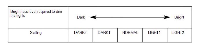
Disp Ex ON Sen |
Changes the ambient brightness level required to dim the lights such as the indicator lights of the combination meter, A/C indicator light and clock.*A |
NORMAL |
000:NORMAL,001:DARK2,010:DARK1,011:LIGHT1,100:LIGHT2 |
Main body ECU (Multiplex network body ECU) |
|
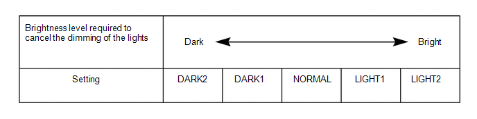
Disp Ex OFF Sen |
Changes the ambient brightness level required to cancel the dimming of the lights such as the indicator lights of the combination meter, A/C indicator light and clock.*B |
NORMAL |
000:NORMAL,001:DARK2,010:DARK1,011:LIGHT1,100:LIGHT2 |
Main body ECU (Multiplex network body ECU) |
|
Light Auto OFF Delay |
Keep the headlights on for a certain period of time after turning the ignition switch off and closing all doors with the low beam headlights on.* |
30s |
00:OFF,01:30 s,10:60 s,11:90 s |
Main body ECU (Multiplex network body ECU) |
|
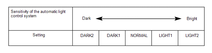
Sensitivity |
Adjusts the sensitivity of the automatic light control system.*C |
Normal |
000:Normal,001:Dark2,010:Dark1,011:Light1,100:Light2 |
Main body ECU (Multiplex network body ECU) |
|
DRL Function |
Turns the DRL system on or off.* |
ON |
0:OFF,1:ON |
Main body ECU (Multiplex network body ECU) |
- *: w/ DRL OFF Switch
HINT:
The sensitivity adjustment may be difficult to confirm. Check by driving the vehicle.
*A
*B
*C
(b) Customizing using the radio and display receiver assembly (for Radio and Display Type) or navigation receiver assembly (for Navigation Receiver Type).
(1) Turn the ignition switch to ON.
(2) Enter the following menus: MENU / Setup / Vehicle / Vehicle Customization / Lights Settings (for Radio and Display Type).
(3) Enter the following menus: APPS / Setup / General / Vehicle / Vehicle Customization / Lights Settings (for Navigation Receiver Type).
(4) Select the setting by referring to the table below.
Lights Settings|
Tester Display |
Description |
Default |
Setting |
ECU |
|---|---|---|---|---|
|
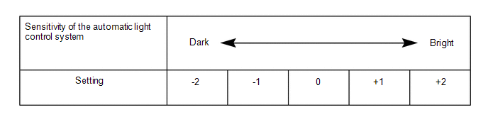
Headlamps-On Sensitivity |
Adjusts the sensitivity of the automatic light control system.*A |
0 |
-2, -1, 0, +1 or +2 |
Main body ECU (Multiplex network body ECU) |
|
Headlamps Auto-Off Timer |
Keep the headlights on for a certain period of time after turning the ignition switch off and closing all doors with the low beam headlights on. |
30 sec. |
Off, 30 sec., 60 sec. or 90 sec. |
Main body ECU (Multiplex network body ECU) |
|
Daytime Running Lights |
Turns the DRL system on or off. |
On |
On or Off |
Main body ECU (Multiplex network body ECU) |
|
Interior Lights Off Timer |
Changes the lighting time after closing all of the doors. (It will fade out immediately in case of turning the ignition switch from off to ACC or ON,) |
15 sec. |
7.5 sec., 15 sec. or 30 sec. |
Main body ECU (Multiplex network body ECU) |
HINT:
The sensitivity adjustment may be difficult to confirm. Check by driving the vehicle.
*A
 System Description
SYSTEM DESCRIPTION
1. ILLUMINATED ENTRY SYSTEM
(a) The illuminated entry system has the following control functions:
Control
Outline
Lights that Operate
...
 How To Proceed With Troubleshooting
CAUTION / NOTICE / HINT
HINT:
Use these procedures to troubleshoot the lighting system.
*: Use the Techstream.
PROCEDURE
1.
VEHICLE BROUGHT TO WORKSHOP
...
Other materials:
Vehicle Information Not Obtained (C1A02)
DESCRIPTION
When a new millimeter wave radar sensor assembly is installed, it receives vehicle
specification information from the main body ECU (multiplex network body ECU) and
stores the information.
DTC C1A02 is stored when the millimeter wave radar sensor assembly receives the
vehicle spe ...
Speed Signal Circuit
DESCRIPTION
The combination meter assembly receives the vehicle speed signal from this circuit.
The wheel speed sensors produce an output that varies according to the vehicle speed.
The wheel speed sensor output is received by the skid control ECU, which uses this
information to create the ve ...
Data List / Active Test
DATA LIST / ACTIVE TEST
1. READ DATA LIST
HINT:
Using the Techstream to read the Data List allows the values or states of switches,
sensors, actuators and other items to be read without removing any parts. This non-intrusive
inspection can be very useful because intermittent conditions or sig ...
