Toyota Tacoma (2015-2018) Service Manual: Parts Location
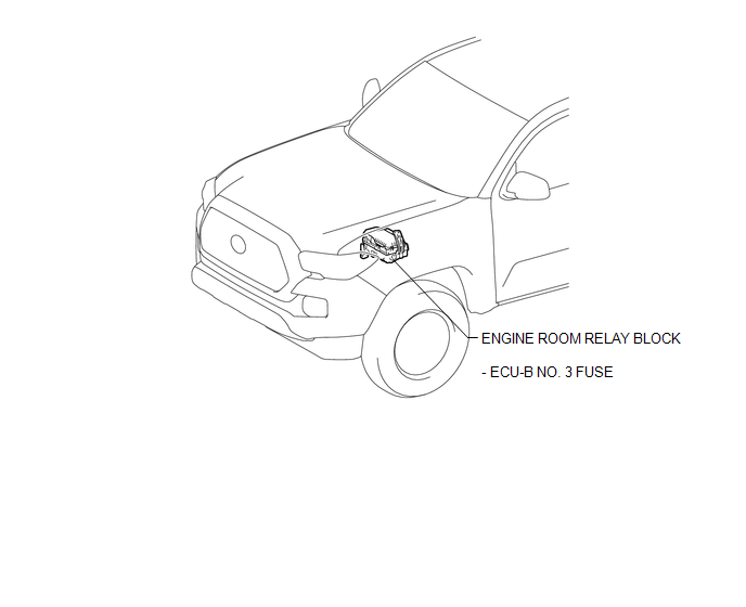
PARTS LOCATION
ILLUSTRATION
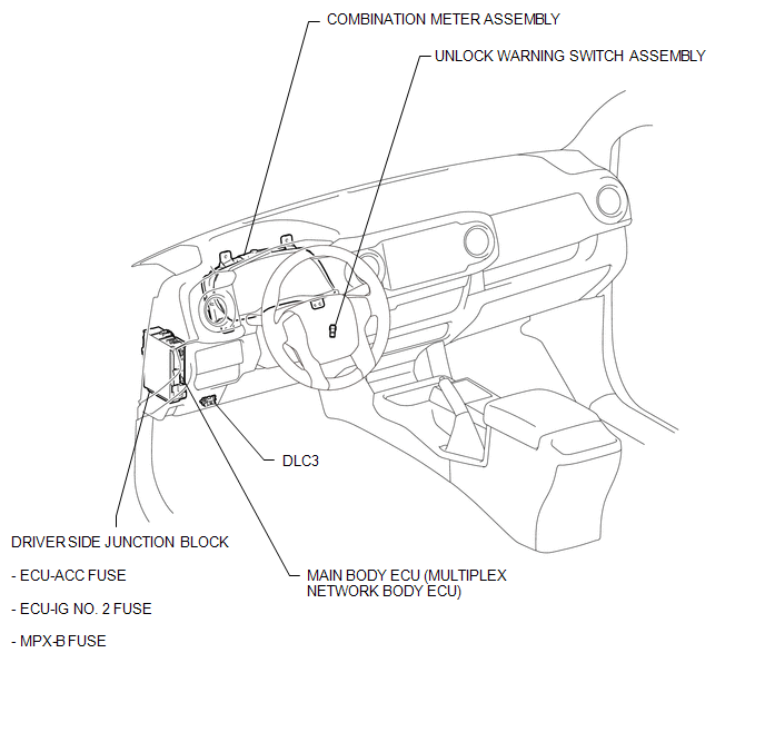
ILLUSTRATION
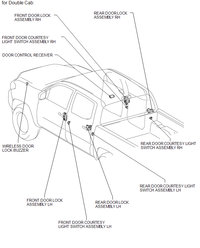
ILLUSTRATION
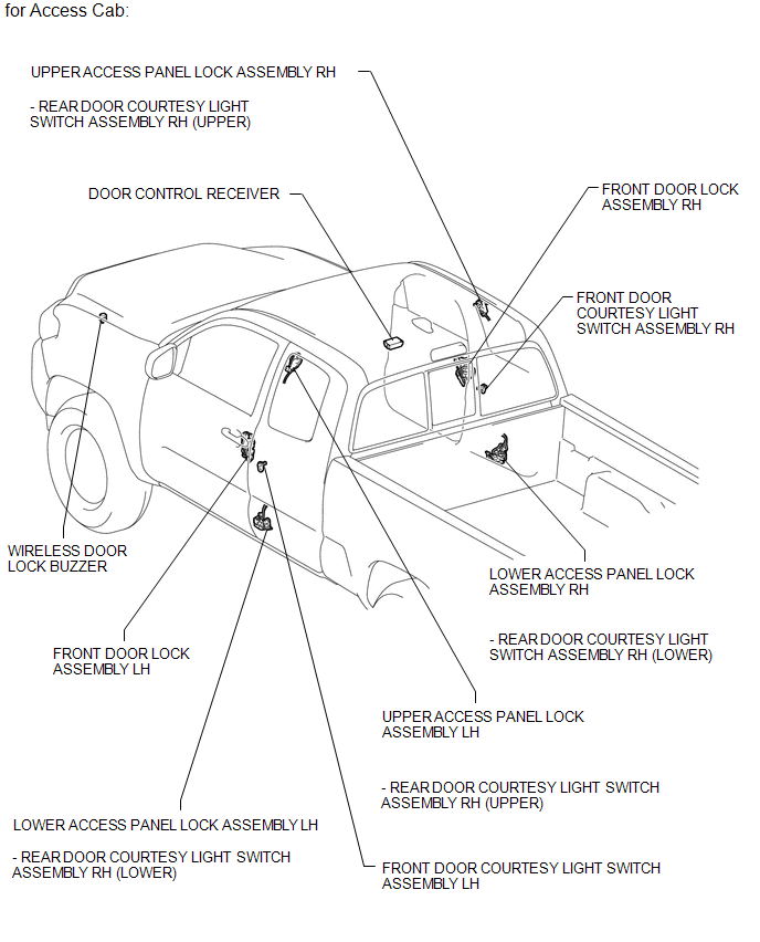
ILLUSTRATION
 Precaution
PRECAUTION
1. DOOR CONTROL RECEIVER EXPRESSIONS
(a) The type of door control receiver used on this model differs according to
the specifications of the vehicle. The expressions listed in the table ...
 System Description
SYSTEM DESCRIPTION
1. WIRELESS DOOR LOCK CONTROL SYSTEM
The wireless door lock control system functions to lock and unlock all the doors
from a distance. The system is controlled by a door control ...
Other materials:
How To Proceed With Troubleshooting
CAUTION / NOTICE / HINT
HINT:
*: Use the Techstream.
PROCEDURE
1.
VEHICLE BROUGHT TO WORKSHOP
NEXT
2.
CUSTOMER PROBLEM ANALYSIS
Click here
(a) Confirm problem s ...
Inspection
INSPECTION
PROCEDURE
1. INSPECT TRANSMISSION FLOOR SHIFT ASSEMBLY (w/o Smart Key System)
HINT:
If the results of the following inspections are as specified but a malfunction
has occurred, replace the transmission floor shift assembly.
(a) Inspect the wire harness.
(1) Disconnect the shift lo ...
Steering Pad Switch
Components
COMPONENTS
ILLUSTRATION
*1
STEERING PAD SWITCH ASSEMBLY
-
-
Removal
REMOVAL
PROCEDURE
1. REMOVE STEERING PAD
(See page )
2. REMOVE STEERING PAD SWITCH ASSEMBLY
(a) Disconnect the 2 connectors.
...
