Toyota Tacoma (2015-2018) Service Manual: Short in GPS Antenna (B15C0,B15C1)
DESCRIPTION
These DTCs are stored when a malfunction occurs in the navigation antenna assembly.
|
DTC No. |
DTC Detection Condition |
Trouble Area |
|---|---|---|
|
B15C0 |
Navigation antenna error |
|
|
B15C1 |
Error of the power source to the navigation antenna |
CAUTION / NOTICE / HINT
NOTICE:
Check that the navigation antenna assembly cable is properly installed and does
not have any sharp bends, pinching or loose connections before performing following
inspection procedure (See page .gif) ).
).
PROCEDURE
|
1. |
CHECK DTC |
(a) Clear the DTCs (See page ).
(b) Recheck for DTCs and check that no DTCs are output.
OK:
No DTCs are output.
| OK | .gif) |
USE SIMULATION METHOD TO CHECK |
|
.gif)
|
2. |
INSPECT NAVIGATION ANTENNA ASSEMBLY |
|
(a) Remove the navigation antenna assembly (See page
|
|
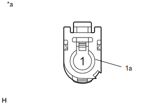
(b) Measure the resistance according to the value(s) in the table below.
Standard Resistance:
|
Tester Connection |
Condition |
Specified Condition |
|---|---|---|
|
1 - 1a |
Always |
50 to 500 Ω |
|
*a |
Component without harness connected (Navigation Antenna Assembly) |
| OK | |
REPLACE RADIO AND DISPLAY RECEIVER ASSEMBLY |
| NG | |
REPLACE NAVIGATION ANTENNA ASSEMBLY |
 AV Signal Stoppage (Low Battery Voltage) (B158F)
DESCRIPTION
This DTC is stored when a video or audio signal is interrupted due to battery
voltage input to the radio and display receiver assembly dropping temporarily.
DTC Code
...
 Speaker Output Short (B15C3)
DESCRIPTION
This DTC is stored when a malfunction occurs in the speakers.
DTC No.
DTC Detection Condition
Trouble Area
B15C3
A short is d ...
Other materials:
Main Owners Manual
Please note that this manual applies to all models explains and all equipment,
including options. Therefore, you may find some explanations for equipment not installed
on your vehicle.
All specifications provided in this manual are current at the time of printing.
However, because of the Toyot ...
Reverse Signal Circuit
DESCRIPTION
The radio and display receiver assembly*1 or navigation receiver assembly*2 receives
a reverse signal from the park/neutral position switch*3 or the back-up light switch
assembly*4.
*1: w/o Navigation System
*2: w/ Navigation System
*3: for Automatic Transmission
...
If the vehicle becomes stuck
Carry out the following procedures if the tires spin or the vehicle becomes
stuck in mud, dirt, or snow.
Stop the engine. Set the parking
brake and put the shift lever in P (vehicles with an automatic transmission) or
N (vehicles with a manual transmission).
Remove the mud, snow, or sand f ...
