Toyota Tacoma (2015-2018) Service Manual: Installation
INSTALLATION
CAUTION / NOTICE / HINT
CAUTION:
Some of these service operations affect the SRS airbag system. Read the precautionary notices concerning the SRS airbag system before servicing.
Click here .gif)
PROCEDURE
1. INSTALL FRONT SEAT INNER BELT ASSEMBLY
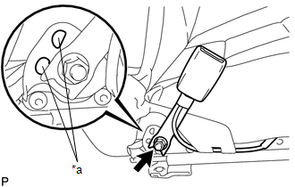
(a) for Driver Side:
(1) Install the front seat belt anchor plate.
|
(2) Install the front seat inner belt assembly with the nut. Text in Illustration
Torque: 42 N·m {428 kgf·cm, 31 ft·lbf} NOTICE: Do not allow the anchor part of the front seat inner belt assembly to overlap the protruding part of the front seat with adjuster frame. |
|
(3) Check that the front seat inner belt rotates smoothly.
(4) Connect the seat position sensor connector.
(5) Engage the 3 clamps.
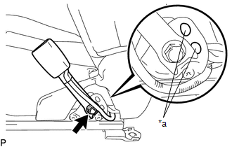
(b) for Front Passenger Side:
(1) Install the front seat belt anchor plate.
|
(2) Install the front seat inner belt assembly with the nut. Text in Illustration
Torque: 42 N·m {428 kgf·cm, 31 ft·lbf} NOTICE: Do not allow the anchor part of the front seat inner belt assembly to overlap the protruding part of the front seat with adjuster frame. |
|
(3) Check that the front seat inner belt rotates smoothly.
(4) Engage the 2 clamps.
(5) Connect the connector.
2. INSTALL FRONT SEAT ASSEMBLY
(a) for Driver Side:
Click here
(b) for Front Passenger Side:
Click here
3. INSTALL SEAT TRACK COVER
(a) for Driver Side:
Click here
(b) for Front Passenger Side:
Click here
4. CONNECT CABLE TO NEGATIVE BATTERY TERMINAL
Torque:
5.4 N·m {55 kgf·cm, 48 in·lbf}
NOTICE:
When disconnecting the cable, some systems need to be initialized after the cable is reconnected.
Click here
5. INSPECT SRS WARNING LIGHT
Click here
 Removal
REMOVAL
CAUTION / NOTICE / HINT
CAUTION:
Some of these service operations affect the SRS airbag system. Read the precautionary
notices concerning the SRS airbag system before servicing.
Click he ...

Other materials:
Disassembly
DISASSEMBLY
PROCEDURE
1. REMOVE HOOD BULGE ASSEMBLY (w/ Hood Bulge)
(a) Remove the 4 nuts.
(b) Disengage the clip from back side of the hood panel to remove the hood bulge
assembly together with the air intake guide.
2. REMOVE NO. 2 HOOD BU ...
Installation
INSTALLATION
PROCEDURE
1. INSTALL FRONT CONSOLE BOX (for Automatic Transmission)
(a) When installing a new front console box:
Text in Illustration
*a
Runner Portion
*b
Cut Off
(1) Usin ...
Windshield wipers and washer
■ Without intermittent type
Type A
Low speed windshield wiper
operation
High speed windshield wiper operation
Temporary operation
Washer operation
Type B
Low speed windshield wiper operation
High speed windshield wiper operation
Temporary operation
Washer op ...
