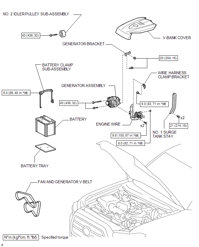
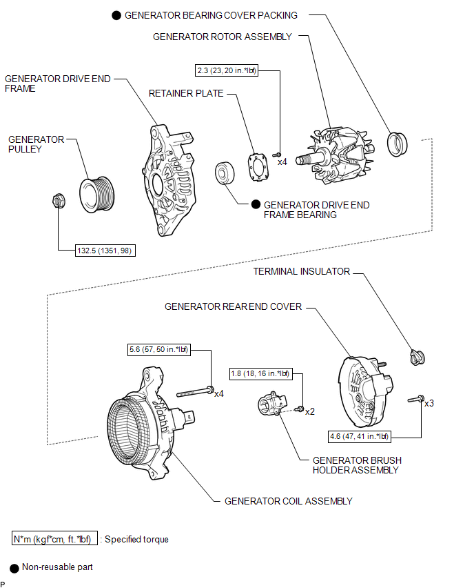
REMOVAL
PROCEDURE
1. PRECAUTION
NOTICE:
After turning the ignition switch off, waiting time may be required before disconnecting
the cable from the negative (-) battery terminal. Therefore, make ...
Related Tacoma materials
How To Proceed With Troubleshooting
CAUTION / NOTICE / HINT
HINT:
Use the following procedure to troubleshoot the wireless charging system.
PROCEDURE
1.
VEHICLE BROUGHT TO WORKSHOP
NEXT
2.
CUSTOMER PROBLEM ANALY ...
Parts Location
PARTS LOCATION
ILLUSTRATION
ILLUSTRATION
ILLUSTRATION
ILLUSTRATION
ILLUSTRATION
...
Reassembly
REASSEMBLY
PROCEDURE
1. INSTALL STARTER ARMATURE ASSEMBLY
(a) Install the starter armature to the starter yoke.
2. INSTALL STARTER BRUSH HOLDER ASSEMBLY
(a) Install the starter brush holder assembly.
(b) Connect the 4 brushes to the starter brush holder assembly.
(1) Using a scre ...