Toyota Tacoma (2015-2018) Service Manual: Components
COMPONENTS
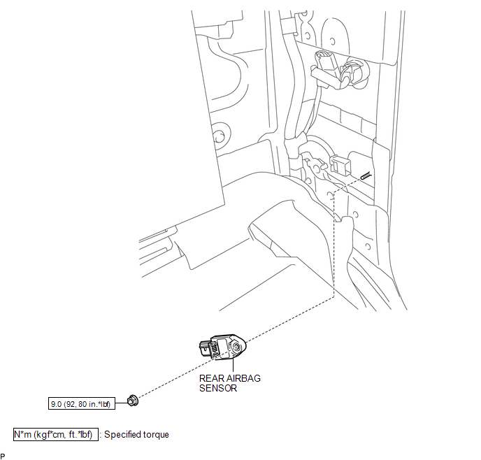
ILLUSTRATION

 Installation
INSTALLATION
CAUTION / NOTICE / HINT
HINT:
Use the same procedure for both the RH and LH sides.
The procedure described below is for the LH side.
PROCEDURE
1. INSTALL REAR AIRBA ...
Other materials:
Open in Front Floor Electrical Key Oscillator Circuit (B27A5)
DESCRIPTION
The certification ECU (smart key ECU assembly) generates a request signal and
transmits the signal to the No. 1 indoor electrical key antenna assembly (front
floor). For the No. 1 indoor electrical key antenna assembly (front floor) to detect
when the electrical key transmitter su ...
Data List / Active Test
DATA LIST / ACTIVE TEST
1. DATA LIST
HINT:
Using the Techstream to read the Data List allows the values or states of switches,
sensors, actuators and other items to be read without removing any parts. This non-intrusive
inspection can be very useful because intermittent conditions or signals ...
Air conditioning filter
The air conditioning filter must be changed regularly to maintain air conditioning
efficiency.
■ Removal method
Turn the engine switch to the LOCK
position.
Open the glove box.
Slide off the damper.
Push in each side of the glove box to disconnect the claws.
Open the filter ...
