Toyota Tacoma (2015-2018) Service Manual: Air Fuel Ratio Sensor
Components
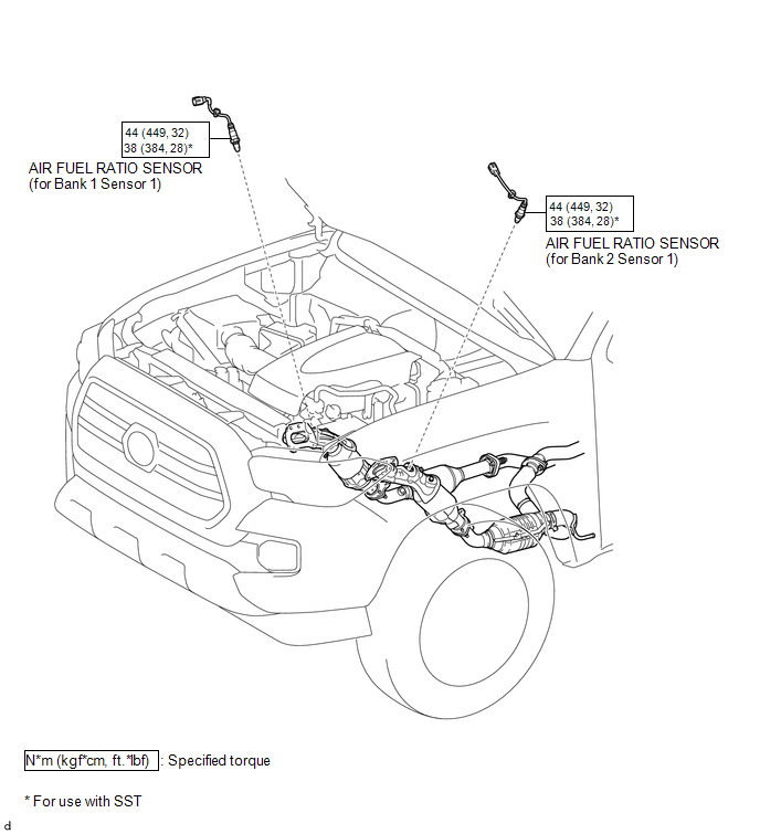
COMPONENTS
ILLUSTRATION
Removal
REMOVAL
PROCEDURE
1. REMOVE AIR FUEL RATIO SENSOR (for Bank 1 Sensor 1)
|
(a) Disconnect the air fuel ratio sensor connector. |
|
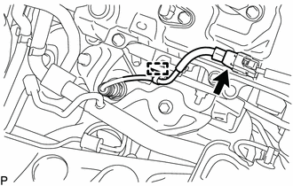
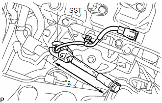
(b) Disengage the clamp to separate the air fuel ratio sensor wire.
|
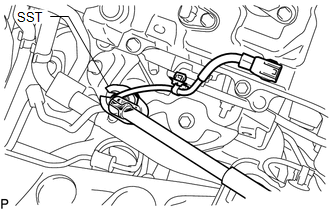
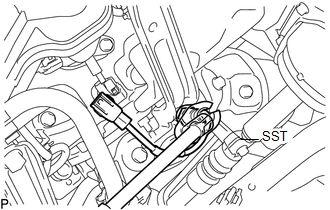
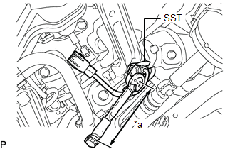
(c) Using SST, remove the air fuel ratio sensor from the exhaust manifold sub-assembly RH. SST: 09224-00011 |
|
2. REMOVE AIR FUEL RATIO SENSOR (for Bank 2 Sensor 1)
|
(a) Disconnect the air fuel ratio sensor connector. |
|
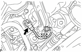
(b) Disengage the clamp to separate the air fuel ratio sensor wire.
|
(c) Using SST, remove the air fuel ratio sensor from the exhaust manifold sub-assembly LH. SST: 09224-00011 |
|
Inspection
INSPECTION
PROCEDURE
1. INSPECT AIR FUEL RATIO SENSOR
|
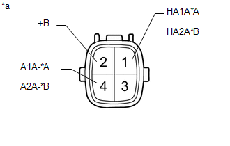
(a) Measure the resistance according to the value(s) in the table below. Text in Illustration
Standard Resistance (for Bank 1 Sensor 1):
Standard Resistance (for Bank 2 Sensor 1):
If the result is not as specified, replace the air fuel ratio sensor. |
|
Installation
INSTALLATION
PROCEDURE
1. INSTALL AIR FUEL RATIO SENSOR (for Bank 1 Sensor 1)
HINT:
Perform "Inspection After Repair" after replacing the air fuel ratio sensor (See
page .gif) ).
).
|
(a) Using SST, install the air fuel ratio sensor to the exhaust manifold sub-assembly RH. Text in Illustration
SST: 09224-00011 Torque: Specified tightening torque : 44 N·m {449 kgf·cm, 32 ft·lbf} HINT:
|
|
(b) Engage the clamp to install the air fuel ratio sensor wire.
(c) Connect the air fuel ratio sensor connector.
2. INSTALL AIR FUEL RATIO SENSOR (for Bank 2 Sensor 1)
HINT:
Perform "Inspection After Repair" after replacing the air fuel ratio sensor (See
page ).
|
(a) Using SST, install the air fuel ratio sensor to the exhaust manifold sub-assembly LH. Text in Illustration
SST: 09224-00011 Torque: Specified tightening torque : 44 N·m {449 kgf·cm, 32 ft·lbf} HINT:
|
|
(b) Engage the clamp to install the air fuel ratio sensor wire.
(c) Connect the air fuel ratio sensor connector.
 Accelerator Pedal
Components
COMPONENTS
ILLUSTRATION
On-vehicle Inspection
ON-VEHICLE INSPECTION
PROCEDURE
1. INSPECT ACCELERATOR PEDAL SENSOR ASSEMBLY
(a) Connect the Techstream to the DLC3.
(b) Turn the ...

Other materials:
Inspection
INSPECTION
PROCEDURE
1. INSPECT AIR CONDITIONING CONTROL ASSEMBLY
(a) Check the blower switch resistance.
(1) Measure the resistance according to the value(s) in the table below.
Text in Illustration
*a
Component without harness connected
...
Disposal
DISPOSAL
CAUTION / NOTICE / HINT
CAUTION:
Before performing pre-disposal deployment of any SRS part, review and closely
follow all applicable environmental and hazardous material regulations. Predisposal
deployment may be considered hazardous material treatment.
PROCEDURE
1. PRECAUTION
...
Power Source Circuit
DESCRIPTION
This circuit provides power to operate the blind spot monitor sensor.
WIRING DIAGRAM
CAUTION / NOTICE / HINT
NOTICE:
Inspect the fuses for circuits related to this system before performing the following
inspection procedure.
PROCEDURE
1.
CHECK HARNESS AN ...
