Toyota Tacoma (2015-2018) Service Manual: Components
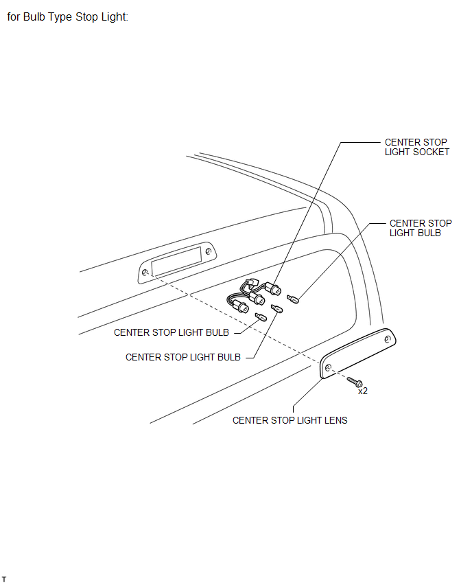
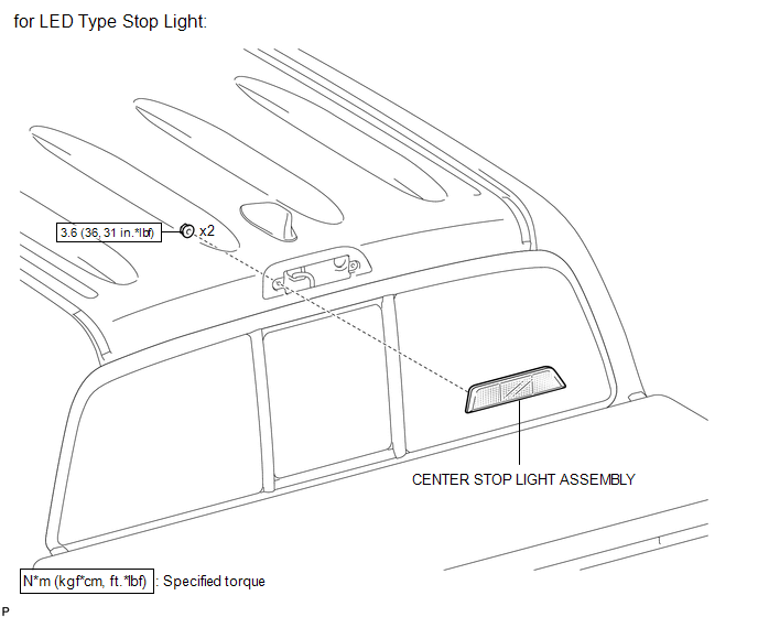
COMPONENTS
ILLUSTRATION
ILLUSTRATION

 Inspection
INSPECTION
PROCEDURE
1. INSPECT CENTER STOP LIGHT ASSEMBLY (for LED Type Stop Light)
(a) Check the illuminates.
(1) Apply battery voltage to the connector and check the light illuminati ...
Other materials:
Identification Information
Vehicle Identification And Serial Numbers
VEHICLE IDENTIFICATION AND SERIAL NUMBERS
1. VEHICLE IDENTIFICATION NUMBER
(a) The vehicle identification number is stamped on the vehicle body and on the
certification label, as shown in the illustration.
A:
Vehicle Identification Number
B:
C ...
System Diagram
SYSTEM DIAGRAM
Communication Table
Transmitting ECU (Transmitter)
Receiving ECU (Receiver)
Signal
Line
Main body ECU
(Multiplex Network Body ECU)
Combination Meter Assembly
Wireless door lock hazard warnin ...
Engine Switch
Components
COMPONENTS
ILLUSTRATION
Inspection
INSPECTION
PROCEDURE
1. INSPECT ENGINE SWITCH
(a) Measure the resistance according to the value(s) in the table below.
Text in Illustration
*a
Component without harness connected
(Engine Switch)
-
...
