Toyota Tacoma (2015-2018) Service Manual: System Diagram
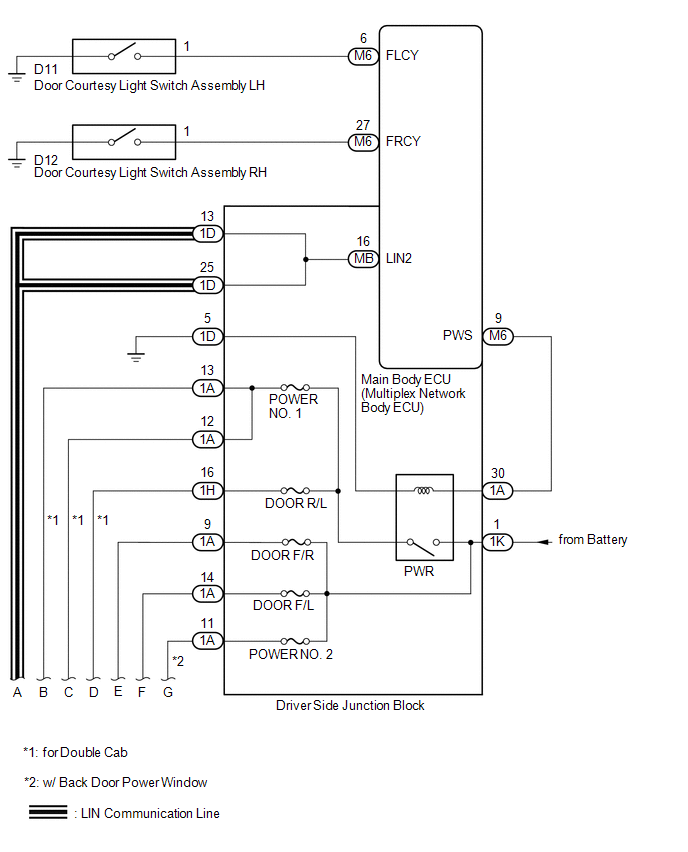
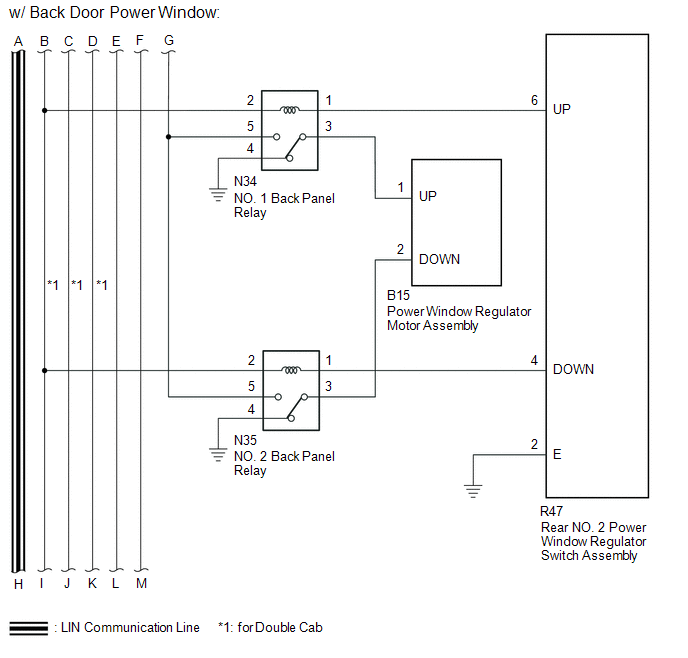
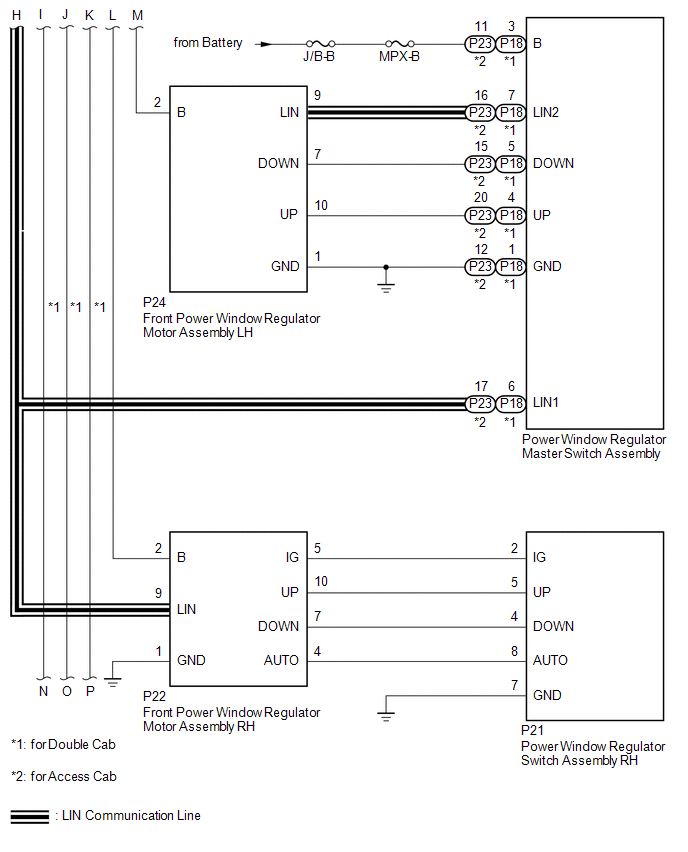
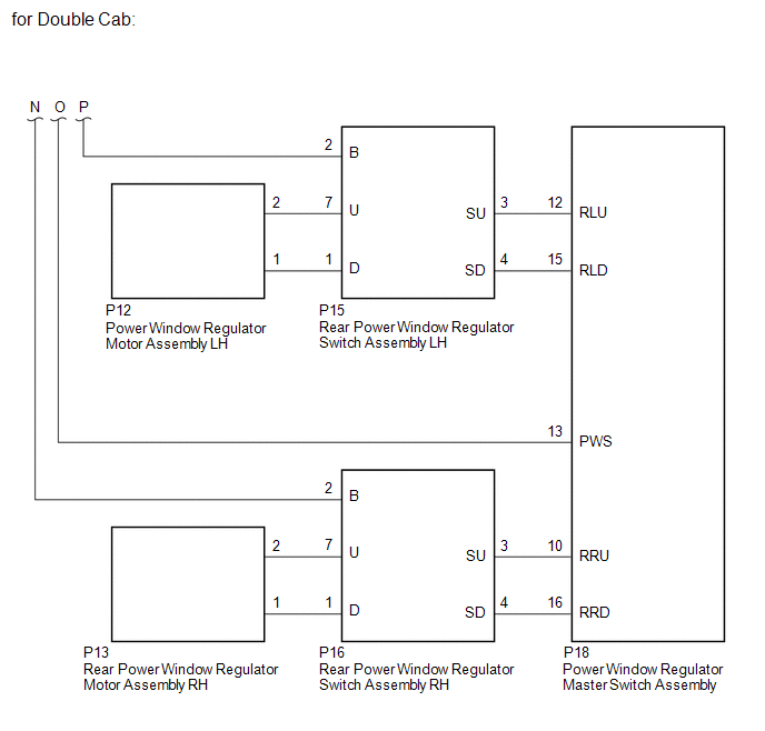
SYSTEM DIAGRAM
 Communication Table
|
Transmitting ECU |
Receiving ECU |
Signal |
Communication Method |
|---|---|---|---|
|
Power Window Regulator Master Switch Assembly |
Power Window Regulator Motor Assembly (for Driver Door) |
Power Window Regulator Motor Assembly (for Front Passenger Door) |
LIN |
|
Power Window Regulator Motor Assembly (for Front Passenger Door) |
Power window remote up and down signal |
LIN |
|
|
Main body ECU (multiplex network body ECU) |
|
Power window operation permission signal |
LIN |
 System Description
SYSTEM DESCRIPTION
1. POWER WINDOW CONTROL SYSTEM DESCRIPTION
(a) The power window control system controls the power window operation using
the power window regulator motors. The main controls of ...
 Customize Parameters
CUSTOMIZE PARAMETERS
PROCEDURE
1. CUSTOMIZE POWER WINDOW CONTROL SYSTEM
HINT:
The following items can be customized.
NOTICE:
When the customer requests a change in a function, first make ...
Other materials:
Starting System
Parts Location
PARTS LOCATION
ILLUSTRATION
ILLUSTRATION
Precaution
PRECAUTION
1. IGNITION SWITCH EXPRESSIONS
(a) The type of ignition switch used on this model differs depending on the specifications
of the vehicle. The expressions listed in the table below are used in this section. ...
Problem Symptoms Table
PROBLEM SYMPTOMS TABLE
HINT:
If a problem occurs in certain locations or at certain times of day,
check for the possibility of wave interference.
When the electrical key transmitter sub-assembly is brought near the
electrical key and TPMS receiver assembly (RF band), front outs ...
Diagnostic Trouble Code Chart
DIAGNOSTIC TROUBLE CODE CHART
Manual Transmission System
DTC Code
Detection Item
MIL
Memory
See page
P03352A
Crankshaft Position Sensor "A" Signal Stuck in Range
Does not come on
DTC ...
