Toyota Tacoma (2015-2018) Service Manual: Components
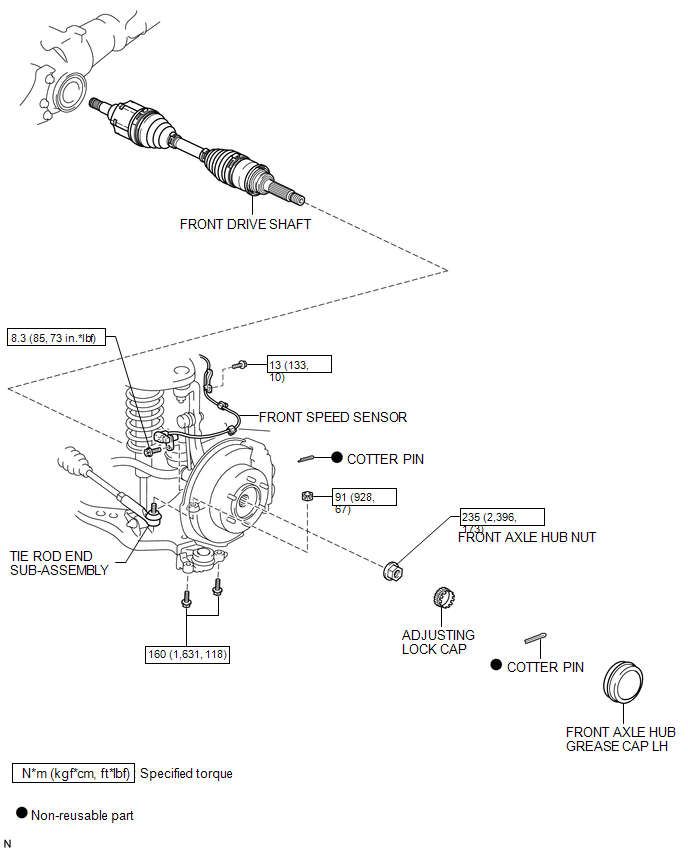
COMPONENTS
ILLUSTRATION
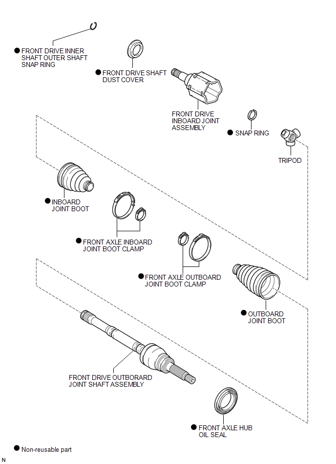
ILLUSTRATION

 Disassembly
DISASSEMBLY
PROCEDURE
1. INSPECT FRONT DRIVE SHAFT
(a) Check whether there is no remarkable play in the outboard joint.
(b) Check whether the inboard joint slides smoothly in the thrust directio ...
Other materials:
Anti-glare inside rear view mirror
Glare from the headlights of vehicles behind can be reduced by using the following
functions.
Manual anti-glare inside rear view
mirror
Normal position
Anti-glare position
Auto anti-glare inside rear view
mirror (type A)
In automatic mode, sensors are used to detect the headlights of ...
Meter Illumination does not Dim at Night
DESCRIPTION
In this circuit, the combination meter assembly auto dimmer signals from the
main body ECU using the CAN communication system (CAN V1 Bus). When the combination
meter assembly an auto dimmer signal, it dims the meter illumination (warning and
indicator lights). The main body ECU ( ...
ECM Communication Stop Mode
DESCRIPTION
Detection Item
Symptom
Trouble Area
ECM Communication Stop Mode
Either condition is met:
Communication stop for "ECM (Engine)" is indicated on the "Communication
Bus Check" screen of the ...
