Toyota Tacoma (2015-2018) Service Manual: Brake Switch "A" Signal Compare Failure (P057162)
DESCRIPTION
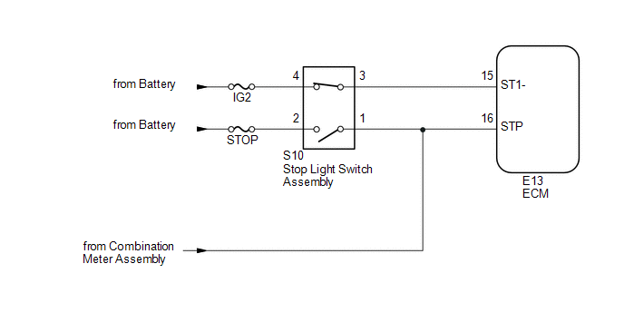
When the brake pedal is depressed, stop light switch assembly sends a signal to the ECM. Upon receiving the signal, the ECM cancels the cruise control system.
|
DTC Code |
DTC Detection Condition |
Trouble Area |
MIL |
Note |
|---|---|---|---|---|
|
P057162 |
|
|
Does not come on |
SAE: P0571 |
WIRING DIAGRAM
CAUTION / NOTICE / HINT
NOTICE:
Inspect the fuses for circuits related to this system before performing the following procedure.
PROCEDURE
|
1. |
CHECK HARNESS AND CONNECTOR (STOP LIGHT SWITCH ASSEMBLY - BATTERY) |
|
(a) Disconnect the stop light switch assembly connector. |
|
(b) Measure the voltage according to the value(s) in the table below.
Standard Voltage:
|
Tester Connection |
Switch Condition |
Specified Condition |
|---|---|---|
|
S10-2 - Body ground |
Always |
11 to 14 V |
|
S10-4 - Body ground |
Ignition switch on |
11 to 14 V |
|
Ignition switch off |
Below 1 V |
|
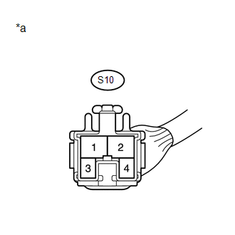
*a |
Front view of wire harness connector (to Stop Light Switch Assembly) |
| NG | .gif) |
REPAIR OR REPLACE HARNESS OR CONNECTOR |
|
.gif)
|
2. |
CHECK HARNESS AND CONNECTOR (STOP LIGHT SWITCH INPUT CIRCUIT) |
|
(a) Disconnect the ECM connector. |
|
(b) Measure the voltage according to the value(s) in the table below.
Standard Voltage:
|
Tester Connection |
Condition |
Specified Condition |
|---|---|---|
|
E13-15 (ST1-) - Body ground |
Ignition switch on, brake pedal released |
7.5 to 14 V |
|
Ignition switch on, brake pedal depressed |
Below 1.5 V |
|
|
E14-10 (STP) - Body ground |
Brake pedal released |
Below 1.5 V |
|
Brake pedal depressed |
7.5 to 14 V |
|
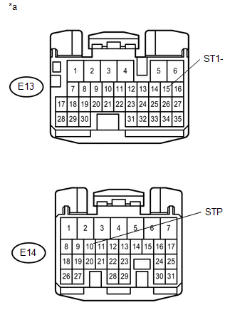
*a |
Front view of wire harness connector (to ECM) |
| NG | |
REPAIR OR REPLACE HARNESS OR CONNECTOR |
|
|
3. |
INSPECT STOP LIGHT SWITCH ASSEMBLY |
(a) Inspect the stop light switch assembly (See page INSPECT STOP LIGHT SWITCH ASSEMBLY ).
(b) Clear the DTCs (See page .gif) ).
).
(c) Check for DTCs (See page ).
OK:
DTC P057162 is not output
| OK | |
REPLACE STOP LIGHT SWITCH ASSEMBLY |
| NG | |
REPLACE ECM |
 Clutch Switch Circuit
DESCRIPTION
Clutch switch circuit inspection is necessary for manual transmission vehicles.
When the clutch pedal is released, the ECM receives the positive (+) battery
voltage through the ECU-IG ...
 Cruise Control Input Processor (P160700)
DESCRIPTION
When the ECM determines that there is a malfunction, the ECM illuminates the
MIL and stores a DTC.
HINT:
When these DTCs are stored, the ECM cuts the current supplied to the throttle ...
Other materials:
Cruise Control System Internal Failure (P057504,P057549)
DESCRIPTION
This is output when the ECM detects malfunctions in the internal circuit.
DTC Code
DTC Detection Condition
Trouble Area
MIL
Note
P057504
Vehicle Condition:
Cruise control in operation
...
Occupant Classification ECU Malfunction (B1795)
DESCRIPTION
DTC B1795 is set when a malfunction is detected in the occupant detection ECU.
Troubleshoot DTC B1771 first when both DTCs B1771 and B1795 are present.
DTC No.
DTC Detections Conditions
Trouble Areas
B1795
Occupant detection ...
Operation Check
OPERATION CHECK
1. NOTICE WHEN CHECKING THE FOLLOWING
(a) Wireless door lock/unlock function:
This wireless door lock control function operates only when the following 3 conditions
are met:
(1) There is no key in the ignition key cylinder.
(2) All doors are closed.
(3) The power door lock sy ...
