Toyota Tacoma (2015-2018) Service Manual: Check Bus 2 Lines for Short Circuit
DESCRIPTION
There may be a short circuit between the CAN main bus lines and/or CAN branch lines when the resistance between terminals 18 (CA4H) and 17 (CA4L) of the central gateway ECU (network gateway ECU) is below 54 Ω.
|
Detection Item |
Trouble Area |
|---|---|
|
Resistance between terminals 18 (CA4H) and 17 (CA4L) of central gateway ECU (network gateway ECU) is below 54 Ω. |
|
- *1: w/ Smart Key System
- *2: for 4WD
- *3: w/ Tire Pressure Warning System and Tire Inflation Pressure Display Function
- *4: for Hydraulic Brake Booster
- *5: for Vacuum Brake Booster
WIRING DIAGRAM
.png)
.png)
CAUTION / NOTICE / HINT
CAUTION:
When performing the confirmation driving pattern, obey all speed limits and traffic laws.
NOTICE:
- Because the order of diagnosis is important to allow correct diagnosis,
make sure to begin troubleshooting using How to Proceed with Troubleshooting
when CAN communication system related DTCs are output.
Click here
.gif)
- Before measuring the resistance of the CAN bus, turn the ignition switch off and leave the vehicle for 1 minute or more without operating the key or any switches, or opening or closing the doors. After that, disconnect the cable from the negative (-) battery terminal and leave the vehicle for 1 minute or more before measuring the resistance.
- After turning the ignition switch off, waiting time may be required
before disconnecting the cable from the negative (-) battery terminal. Therefore,
make sure to read the disconnecting the cable from the negative (-) battery
terminal notices before proceeding with work.
Click here
- Some parts must be initialized and set when replacing or removing and
installing parts.
Click here
- After performing repairs, perform the DTC check procedure and confirm
that the DTCs are not output again.
DTC check procedure: Turn the ignition switch to ON and wait for 1 minute or more. Then operate the suspected malfunctioning system and drive the vehicle at 60 km/h (37 mph) or more for 5 minutes or more.
- After the repair, perform the CAN bus check and check that all the ECUs
and sensors connected to the CAN communication system are displayed as normal.
Click here
- If the main body ECU (multiplex network body ECU) or certification ECU
(smart key ECU assembly) is replaced, refer to Registration.
Click here
HINT:
- Before disconnecting related connectors for inspection, push in on each connector body to check that the connector is not loose or disconnected.
- When a connector is disconnected, check that the terminals and connector body are not cracked, deformed or corroded.
PROCEDURE
|
1. |
CHECK FOR SHORT IN CAN BUS LINES (NO. 1 CAN JUNCTION CONNECTOR) |
(a) Disconnect the cable from the negative (-) battery terminal.
(b) Disconnect the No. 1 CAN junction connector.
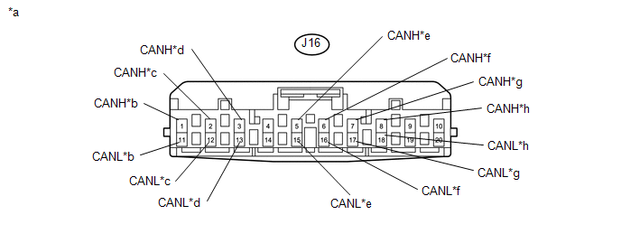 Text in Illustration
|
*a |
Front view of wire harness connector (to No. 1 CAN Junction Connector) |
*b |
to Brake Booster Assembly (Skid Control ECU) (for Hydraulic Brake Booster) or Brake Actuator Assembly (Skid Control ECU) (for Vacuum Brake Booster) |
|
*c |
to No. 2 CAN Junction Connector |
*d |
to Air Conditioning Amplifier Assembly |
|
*e |
to ECM |
*f |
to Central Gateway ECU (Network Gateway ECU) |
|
*g |
to Airbag Sensor Assembly |
*h |
to 4 Wheel Drive Control ECU (for 4WD) |
(c) Measure the resistance according to the value(s) in the table below.
Standard Resistance:
|
Tester Connection |
Condition |
Specified Condition |
Connected to |
|---|---|---|---|
|
J16-1 (CANH) - J16-11 (CANL) |
Cable disconnected from negative (-) battery terminal |
200 Ω or higher |
Brake booster assembly (skid control ECU)*1 or brake actuator assembly (skid control ECU)*2 |
|
J16-2 (CANH) - J16-12 (CANL) |
Cable disconnected from negative (-) battery terminal |
108 to 132 Ω |
No. 2 CAN junction connector |
|
J16-3 (CANH) - J16-13 (CANL) |
Cable disconnected from negative (-) battery terminal |
200 Ω or higher |
Air conditioning amplifier assembly |
|
J16-5 (CANH) - J16-15 (CANL) |
Cable disconnected from negative (-) battery terminal |
108 to 132 Ω |
ECM |
|
J16-6 (CANH) - J16-16 (CANL) |
Cable disconnected from negative (-) battery terminal |
200 Ω or higher |
Central gateway ECU (network gateway ECU) |
|
J16-7 (CANH) - J16-17 (CANL) |
Cable disconnected from negative (-) battery terminal |
200 Ω or higher |
Airbag sensor assembly |
|
J16-8 (CANH) - J16-18 (CANL) |
Cable disconnected from negative (-) battery terminal |
200 Ω or higher |
4 wheel drive control ECU*3 |
- *1: for Hydraulic Brake Booster
- *2: for Vacuum Brake Booster
- *3: for 4WD
|
Result |
Proceed to |
|---|---|
|
OK |
A |
|
NG (ECM CAN main line) |
B |
|
NG (Central gateway ECU (network gateway ECU) CAN branch line) |
C |
|
NG (No. 2 CAN junction connector CAN main line) |
D |
|
NG (ECU or sensor CAN branch lines) |
E |
| A | .gif) |
REPLACE NO. 1 CAN JUNCTION CONNECTOR |
| B | |
REPAIR OR REPLACE CAN MAIN LINE OR CONNECTOR (NO. 1 CAN JUNCTION CONNECTOR - ECM) |
| D | |
GO TO STEP 3 |
| E | |
GO TO STEP 4 |
|
.gif)
|
2. |
CHECK FOR SHORT IN CAN BUS LINES (NO. 1 CAN JUNCTION CONNECTOR - CENTRAL GATEWAY ECU (NETWORK GATEWAY ECU)) |
|
(a) Disconnect the N36 central gateway ECU (network gateway ECU) connector. |
|
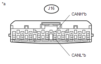
(b) Measure the resistance according to the value(s) in the table below.
Standard Resistance:
|
Tester Connection |
Condition |
Specified Condition |
|---|---|---|
|
J16-6 (CANH) - J16-16 (CANL) |
Cable disconnected from negative (-) battery terminal |
1 MΩ or higher |
|
*a |
Front view of wire harness connector (to No. 1 CAN Junction Connector) |
|
*b |
to Central Gateway ECU (Network Gateway ECU) |
| OK | |
REPLACE CENTRAL GATEWAY ECU (NETWORK GATEWAY ECU) |
| NG | |
REPAIR OR REPLACE CAN BRANCH LINE OR CONNECTOR (NO. 1 CAN JUNCTION CONNECTOR - CENTRAL GATEWAY ECU (NETWORK GATEWAY ECU)) |
|
3. |
CHECK FOR SHORT IN CAN BUS LINES (NO. 2 CAN JUNCTION CONNECTOR) |
(a) Reconnect the J16 No. 1 CAN Junction Connector.
(b) Disconnect the No. 2 CAN junction connector.
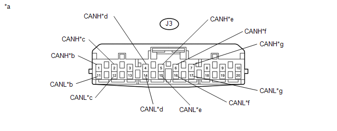 Text in Illustration
|
*a |
Front view of wire harness connector (to No. 2 CAN Junction Connector) |
*b |
to No. 1 CAN Junction Connector |
|
*c |
to Door Control and Tire Pressure Monitoring System Receiver Assembly (w/ Tire Pressure Warning System and Tire Inflation Pressure Display Function) |
*d |
to Main Body ECU (Multiplex Network Body ECU) |
|
*e |
to Certification ECU (Smart Key ECU Assembly) (w/ Smart Key System) |
*f |
to Combination Meter Assembly |
|
*g |
to Spiral Cable with Sensor Sub-assembly |
- |
- |
(c) Measure the resistance according to the value(s) in the table below.
Standard Resistance:
|
Tester Connection |
Condition |
Specified Condition |
Connected to |
|---|---|---|---|
|
J3-1 (CANH) - J3-11 (CANL) |
Cable disconnected from negative (-) battery terminal |
108 to 132 Ω |
No. 1 CAN junction connector |
|
J3-2 (CANH) - J3-12 (CANL) |
Cable disconnected from negative (-) battery terminal |
200 Ω or higher |
Door control and tire pressure monitoring system receiver assembly*1 |
|
J3-4 (CANH) - J3-14 (CANL) |
Cable disconnected from negative (-) battery terminal |
200 Ω or higher |
Main body ECU (multiplex network body ECU) |
|
J3-5 (CANH) - J3-15 (CANL) |
Cable disconnected from negative (-) battery terminal |
200 Ω or higher |
Certification ECU (smart key ECU assembly)*2 |
|
J3-6 (CANH) - J3-16 (CANL) |
Cable disconnected from negative (-) battery terminal |
108 to 132 Ω |
Combination meter assembly |
|
J3-7 (CANH) - J3-17 (CANL) |
Cable disconnected from negative (-) battery terminal |
200 Ω or higher |
Spiral cable with sensor sub-assembly |
- *1: w/ Tire Pressure Warning System and Tire Inflation Pressure Display Function
- *2: w/ Smart Key System
|
Result |
Proceed to |
|---|---|
|
OK |
A |
|
NG (Combination meter assembly CAN main line) |
B |
|
NG (No. 1 CAN junction connector CAN main line) |
C |
|
NG (ECU or sensor CAN branch lines) |
D |
| A | |
REPLACE NO. 2 CAN JUNCTION CONNECTOR |
| B | |
REPAIR OR REPLACE CAN MAIN LINE OR CONNECTOR (NO. 2 CAN JUNCTION CONNECTOR - COMBINATION METER ASSEMBLY) |
| C | |
REPAIR OR REPLACE CAN MAIN LINE OR CONNECTOR (NO. 2 CAN JUNCTION CONNECTOR - NO. 1 CAN JUNCTION CONNECTOR) |
|
|
4. |
CHECK FOR SHORT IN CAN BUS LINES (ECU, SENSOR) |
|
(a) Reconnect the CAN junction connector. |
|
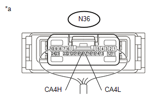
(b) Disconnect the connector that includes terminals CANH and CANL from the ECU or sensor to which the short circuited CAN branch line is connected.
(c) Measure the resistance according to the value(s) in the table below.
Standard Resistance:
|
Tester Connection |
Condition |
Specified Condition |
|---|---|---|
|
N36-18 (CA4H) - N36-17 (CA4L) |
Cable disconnected from negative (-) battery terminal |
54 to 69 Ω |
|
*a |
Component with harness connected (Central Gateway ECU (Network Gateway ECU)) |
HINT:
If the resistance becomes normal (between 54 and 69 Ω) when the connector is disconnected from the ECU or sensor, there may be a short in the ECU or sensor.
| OK | |
REPLACE ECU OR SENSOR |
| NG | |
REPAIR OR REPLACE HARNESS OR CONNECTOR |
 Check Bus 2 Line for Short to +B
DESCRIPTION
There may be a short circuit between one of the CAN bus lines and +B when no
resistance exists between terminal 18 (CA4H) of the central gateway ECU (network
gateway ECU) and terminal ...
 Open in Bus 3 Main Bus Line
DESCRIPTION
There may be an open circuit in one of the CAN main bus lines when the resistance
between terminals 6 (CA3H) and 21 (CA3L) of the central gateway ECU (network gateway
ECU) is 70 Ω or ...
Other materials:
Radio Antenna Cord
Components
COMPONENTS
ILLUSTRATION
Removal
REMOVAL
PROCEDURE
1. REMOVE INSTRUMENT PANEL SUB-ASSEMBLY
(See page )
2. REMOVE ANTENNA CORD SUB-ASSEMBLY
(a) Disengage the 4 clamps to remove the antenna cord sub-assembly.
Installation
INSTALLATION
PROCEDURE
1. INSTALL ANTENNA COR ...
Problem Symptoms Table
PROBLEM SYMPTOMS TABLE
HINT:
Use the table below to help determine the cause of problem symptoms.
If multiple suspected areas are listed, the potential causes of the symptoms
are listed in order of probability in the "Suspected Area" column of the
table. Check each sy ...
Registration
REGISTRATION
PROCEDURE
1. DESCRIPTION OF CODE REGISTRATION
HINT:
Registering an ID code enables the entry and start function, wireless
door lock control function and engine immobiliser function to be operated.
Code registration is needed when the certification ECU (smart key E ...
