Toyota Tacoma (2015-2018) Service Manual: Radio Antenna Cord
Components
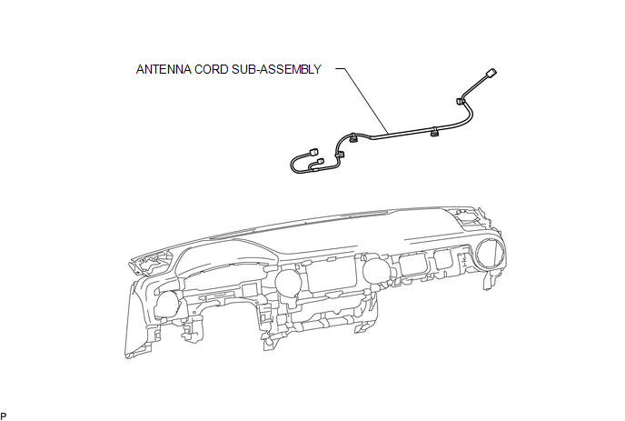
COMPONENTS
ILLUSTRATION
Removal
REMOVAL
PROCEDURE
1. REMOVE INSTRUMENT PANEL SUB-ASSEMBLY
(See page .gif) )
)
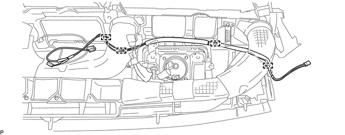
2. REMOVE ANTENNA CORD SUB-ASSEMBLY
(a) Disengage the 4 clamps to remove the antenna cord sub-assembly.
Installation
INSTALLATION
PROCEDURE
1. INSTALL ANTENNA CORD SUB-ASSEMBLY
(a) Engage the 4 clamps to install the antenna cord sub-assembly.
2. INSTALL INSTRUMENT PANEL SUB-ASSEMBLY
(See page .gif) )
)
 Radio Antenna
Components
COMPONENTS
ILLUSTRATION
Removal
REMOVAL
PROCEDURE
1. REMOVE ROOF HEADLINING ASSEMBLY (for Double Cab)
(See page )
2. REMOVE ROOF HEADLINING ASSEMBLY (for Access Cab)
(See p ...
 Radio Receiver
Components
COMPONENTS
ILLUSTRATION
ILLUSTRATION
Removal
REMOVAL
PROCEDURE
1. REMOVE INSTRUMENT CLUSTER CENTER FINISH PANEL SUB-ASSEMBLY
(See page )
2. REMOVE RADIO AND DISPLAY RECEI ...
Other materials:
Short to GND in Outer Mirror Indicator(Slave) (C1AB3)
DESCRIPTION
This DTC is stored when the blind spot monitor sensor RH detects a ground short
in the blind spot monitor indicator RH.
DTC Code
DTC Detection Condition
Trouble Area
C1AB3
With the blind spot monitor main switch assembly (w ...
Horn Relay
On-vehicle Inspection
ON-VEHICLE INSPECTION
PROCEDURE
1. INSPECT HORN RELAY ASSEMBLY
(a) Check the resistance.
(1) Measure the resistance according to the value(s) in the table below.
Standard Resistance:
Tester Connection
Connection
...
Pressure Control Solenoid "D" Electrical (Shift Solenoid Valve SLT) (P2716)
DESCRIPTION
Refer to the system description for DTC P2714 (See page
).
DTC No.
DTC Detection Condition
Trouble Area
P2716
Open or short is detected in shift solenoid valve SLT circuit for 1 second
or more while driving (1 trip dete ...
