Toyota Tacoma (2015-2018) Service Manual: Open in Bus 3 Main Bus Line
DESCRIPTION
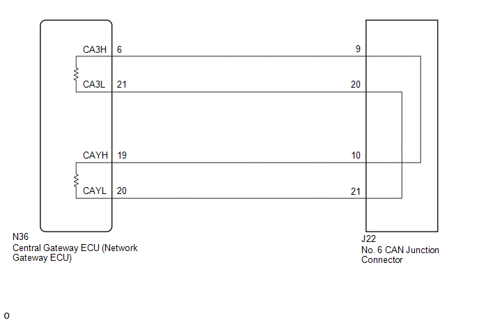
There may be an open circuit in one of the CAN main bus lines when the resistance between terminals 6 (CA3H) and 21 (CA3L) of the central gateway ECU (network gateway ECU) is 70 Ω or higher.
|
Detection Item |
Trouble Area |
|---|---|
|
Resistance between terminals 6 (CA3H) and 21 (CA3L) of central gateway ECU (network gateway ECU) is 70 Ω or higher. |
|
This malfunction is not related to the lines of a CAN branch or to ECUs or sensors connected to a CAN branch.
WIRING DIAGRAM
CAUTION / NOTICE / HINT
CAUTION:
When performing the confirmation driving pattern, obey all speed limits and traffic laws.
NOTICE:
- Because the order of diagnosis is important to allow correct diagnosis,
make sure to begin troubleshooting using How to Proceed with Troubleshooting
when CAN communication system related DTCs are output.
Click here
.gif)
- Before measuring the resistance of the CAN bus, turn the ignition switch off and leave the vehicle for 1 minute or more without operating the key or any switches, or opening or closing the doors. After that, disconnect the cable from the negative (-) battery terminal and leave the vehicle for 1 minute or more before measuring the resistance.
- After turning the ignition switch off, waiting time may be required
before disconnecting the cable from the negative (-) battery terminal. Therefore,
make sure to read the disconnecting the cable from the negative (-) battery
terminal notices before proceeding with work.
Click here
- Some parts must be initialized and set when replacing or removing and
installing parts.
Click here
- After performing repairs, perform the DTC check procedure and confirm
that the DTCs are not output again.
DTC check procedure: Turn the ignition switch to ON and wait for 1 minute or more. Then operate the suspected malfunctioning system and drive the vehicle at 60 km/h (37 mph) or more for 5 minutes or more.
- After the repair, perform the CAN bus check and check that all the ECUs
and sensors connected to the CAN communication system are displayed as normal.
Click here
HINT:
- Before disconnecting related connectors for inspection, push in on each connector body to check that the connector is not loose or disconnected.
- When a connector is disconnected, check that the terminals and connector body are not cracked, deformed or corroded.
PROCEDURE
|
1. |
CHECK FOR OPEN IN CAN BUS LINES (NO. 6 CAN JUNCTION CONNECTOR) |
(a) Disconnect the cable from the negative (-) battery terminal.
|
(b) Disconnect the No. 6 CAN junction connector. |
|
(c) Measure the resistance according to the value(s) in the table below.
Standard Resistance:
|
Tester Connection |
Condition |
Specified Condition |
Connected to |
|---|---|---|---|
|
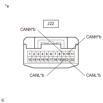
J22-9 (CANH) - J22-20 (CANL) |
Cable disconnected from negative (-) battery terminal |
108 to 132 Ω |
Central gateway ECU (network gateway ECU) |
|
J22-10 (CANH) - J22-21 (CANL) |
Cable disconnected from negative (-) battery terminal |
108 to 132 Ω |
Central gateway ECU (network gateway ECU) |
|
*a |
Front view of wire harness connector (to No. 6 CAN Junction Connector) |
|
*b |
to Central Gateway ECU (Network Gateway ECU) |
| OK | .gif) |
REPLACE NO. 6 CAN JUNCTION CONNECTOR |
|
.gif)
|
2. |
CHECK FOR OPEN IN CAN BUS LINES (CENTRAL GATEWAY ECU (NETWORK GATEWAY ECU) - NO. 6 CAN JUNCTION CONNECTOR) |
(a) Reconnect the J22 No. 6 CAN junction connector.
|
(b) Disconnect the central gateway ECU (network gateway ECU) connector. |
|
(c) Measure the resistance according to the value(s) in the table below.
Standard Resistance:
|
Tester Connection |
Condition |
Specified Condition |
|---|---|---|
|
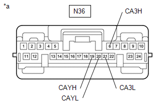
N36-6 (CA3H) - N36-19 (CAYH) |
Cable disconnected from negative (-) battery terminal |
Below 1 Ω |
|
N36-21 (CA3L) - N36-20 (CAYL) |
Cable disconnected from negative (-) battery terminal |
Below 1 Ω |
|
*a |
Front view of wire harness connector (to Central Gateway ECU (Network Gateway ECU)) |
| OK | |
REPLACE CENTRAL GATEWAY ECU (NETWORK GATEWAY ECU) |
| NG | |
REPAIR OR REPLACE CAN MAIN BUS LINES OR CONNECTOR (CENTRAL GATEWAY ECU (NETWORK GATEWAY ECU) - NO. 6 CAN JUNCTION CONNECTOR) |
 Check Bus 2 Lines for Short Circuit
DESCRIPTION
There may be a short circuit between the CAN main bus lines and/or CAN branch
lines when the resistance between terminals 18 (CA4H) and 17 (CA4L) of the central
gateway ECU (network g ...
 Open in One Side of Bus 2 Branch Line
DESCRIPTION
When the CAN bus main lines are normal (no open, short to ground, short to +B
or short between lines) and there is an ECU or sensor on the "Communication Bus
Check" screen t ...
Other materials:
Open in Occupant Classification ECU Battery Positive Line (B1794)
DESCRIPTION
DTC B1794 is set when a malfunction is detected in the occupant detection ECU.
DTC No.
DTC Detections Conditions
Trouble Areas
B1794
Occupant detection ECU circuit malfunction
Occupant detection ECU malfuncti ...
4WD Control Switch Circuit
WIRING DIAGRAM
PROCEDURE
1.
CONFIRM PROBLEM SYMPTOM
(a) Confirm the problem symptoms.
Result
Result
Proceed to
The 4WD indicator light (green) and 4LO indicator light remain off
A
The 4WD indica ...
Reassembly
REASSEMBLY
PROCEDURE
1. INSTALL FRONT OIL PUMP OIL SEAL
(a) Using SST and a hammer, install a new front oil pump oil seal to
the front oil pump body sub-assembly.
SST: 09350-30020
09351-32140
Standard depth:
-0.3 to 0.3 mm (-0.0118 to 0.0118 in.)
...
