Toyota Tacoma (2015-2018) Service Manual: Removal
REMOVAL
PROCEDURE
1. PRECAUTION
NOTICE:
After turning the ignition switch off, waiting time may be required before disconnecting the cable from the battery terminal. Therefore, make sure to read the disconnecting the cable from the battery terminal notice before proceeding with work.
Click here .gif)
2. DISCHARGE FUEL SYSTEM PRESSURE
Click here
3. DISCONNECT CABLE FROM NEGATIVE BATTERY TERMINAL
NOTICE:
When disconnecting the cable, some systems need to be initialized after the cable is reconnected.
Click here
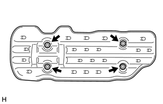
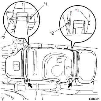
4. REMOVE NO. 1 FUEL TANK PROTECTOR SUB-ASSEMBLY (for Hydraulic Brake Booster)
|
(a) Remove the 4 nuts and No. 1 fuel tank protector sub-assembly. |
|
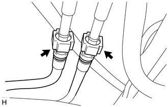
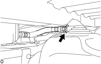
5. DISCONNECT FUEL TANK MAIN TUBE SUB-ASSEMBLY
|
(a) Remove the fuel pipe clamp. |
|
|
(b) Disconnect the fuel tank main tube sub-assembly. Click here |
|
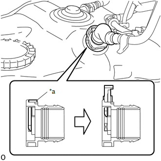
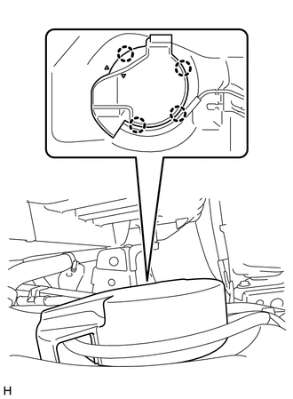
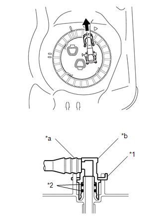
6. DISCONNECT FUEL TANK INLET PIPE SUB-ASSEMBLY
|
(a) Pry up the retainer of quick connector and disconnect the fuel tank inlet pipe sub-assembly from the fuel tank assembly. NOTICE:
|
|
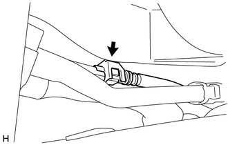
7. DISCONNECT FUEL TANK VENT HOSE SUB-ASSEMBLY
|
(a) Disconnect the fuel tank vent hose sub-assembly. Click here |
|
8. REMOVE FUEL TANK ASSEMBLY
|
(a) Disconnect the fuel breather tube. Click here |
|
|
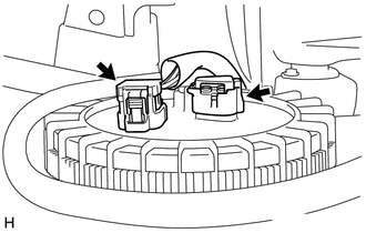
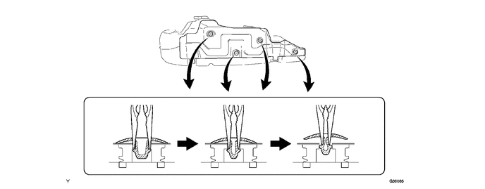
(b) w/ Fuel Tank Cover: (1) Disengage the 4 claws and remove the fuel tank cover. |
|
|
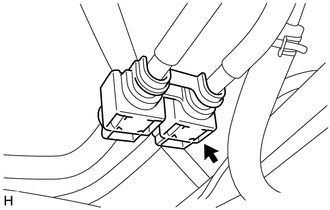
(c) Disconnect the 2 fuel suction tube with pump and gauge assembly connectors. |
|
(d) Hold the fuel tank using the engine lifter.
|
(e) Remove the 2 fuel tank bands. (1) Remove the 2 bolts. (2) Remove the 2 clips, 2 pins and 2 fuel tank bands. |
|
(f) Slowly lower the engine lifter slightly.
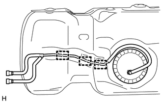
9. REMOVE FUEL TANK MAIN TUBE SUB-ASSEMBLY
|
(a) Remove the tube joint clip and pull out the fuel tank main tube sub-assembly. NOTICE:
|
|
|
(b) Disengage the 3 clamps and remove the fuel tank main tube sub-assembly from the fuel tank sub-assembly. |
|
10. REMOVE FUEL PUMP GAUGE RETAINER
Click here
11. REMOVE FUEL SUCTION TUBE WITH PUMP AND GAUGE ASSEMBLY
Click here
12. REMOVE FUEL SUCTION TUBE SET GASKET
Click here
13. DRAIN FUEL
14. REMOVE NO. 1 FUEL TANK PROTECTOR
(a) Remove the 4 clips and No. 1 fuel tank protector.
 Components
COMPONENTS
ILLUSTRATION
*A
w/ Fuel Tank Cover
*B
for Hydraulic Brake Booster
*1
FUEL TANK ASSEMBLY
*2
...
 Installation
INSTALLATION
PROCEDURE
1. INSTALL NO. 1 FUEL TANK PROTECTOR
(a) Install the No. 1 fuel tank protector to the fuel tank assembly with the
4 clips.
2. INSTALL FUEL SUCTION TUBE SET GASKET
Click h ...
Other materials:
System Diagram
SYSTEM DIAGRAM
Communication Table
Transmitting ECU (Transmitter)
Receiving ECU (Receiver)
Signal
Line
Main body ECU
(Multiplex Network Body ECU)
Combination Meter Assembly
Wireless door lock hazard warnin ...
On-vehicle Inspection
ON-VEHICLE INSPECTION
PROCEDURE
1. INSPECT COOLER CONDENSER ASSEMBLY
(a) If the fins of the cooler condenser assembly are dirty, clean them with water
and dry them with compressed air.
NOTICE:
Do not damage the fins of the condenser assembly.
(b) If the fins of the cooler condenser assembly ...
Test Mode Procedure
TEST MODE PROCEDURE
1. TEST MODE PROCEDURE (for Using Techstream)
HINT:
If the ignition switch is turned from the ON to the ACC or LOCK position
during test mode, DTCs related to the signal check function will be cleared.
During test mode, the skid control ECU (master cylinder ...
