Toyota Tacoma (2015-2018) Service Manual: Speed Signal Malfunction (B15C2)
DESCRIPTION
The navigation receiver assembly receives a vehicle speed signal from the combination meter assembly and information from the navigation antenna assembly, and then adjusts the vehicle position.
The navigation receiver assembly stores this DTC when the difference between the speed information that the navigation antenna assembly receives and the SPD pulse received from the combination meter assembly becomes large.
HINT:
- A voltage of 12 V or 5 V is output from each ECU and then input to the combination meter assembly. The signal is changed to a pulse signal at the transistor in the combination meter assembly. Each ECU controls the respective systems based on the pulse signal.
- If a short occurs in any of the ECUs or in the wire harness connected to an ECU, all systems in the diagram below will not operate normally.
|
DTC Code |
DTC Detection Condition |
Trouble Area |
|---|---|---|
|
B15C2 |
A difference between the GPS speed and SPD pulse is detected. |
|
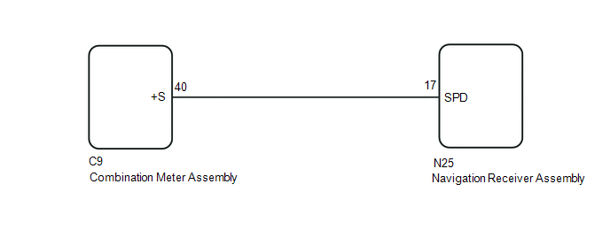
WIRING DIAGRAM
PROCEDURE
|
1. |
CHECK VEHICLE SENSOR (OPERATION CHECK) |
|
(a) Enter the "System Sensors Check" screen. Refer to Check GPS & Vehicle
Sensors in Operation Check (See page |
|
.gif) ).
).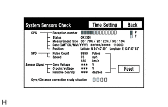
(b) While driving the vehicle, compare the "Speed" indicator to the reading on the speedometer. Check if these readings are almost equal.
OK:
The readings are equal or almost equal.
| OK | .gif) |
REPLACE NAVIGATION RECEIVER ASSEMBLY |
|
.gif)
|
2. |
CHECK COMBINATION METER ASSEMBLY (OUTPUT WAVEFORM) |
|
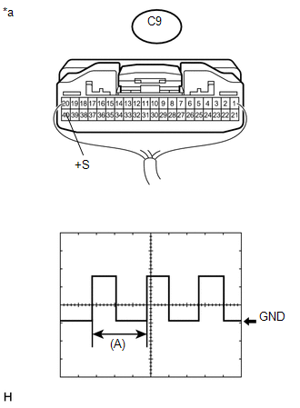
(a) Check the output waveform. (1) Remove the combination meter assembly with the connector(s) still connected. (2) Connect an oscilloscope to terminal C9-40 (+S) and body ground. (3) Turn the ignition switch to ON. (4) Turn a wheel slowly. (5) Check the signal waveform according to the condition(s) in the table below.
OK: The waveform is similar to that shown in the illustration. HINT: When the system is functioning normally, one wheel revolution generates 4 pulses. As the vehicle speed increases, the width indicated by (A) in the illustration narrows. Text in Illustration
|
|
| NG | |
GO TO METER / GAUGE SYSTEM |
|
|
3. |
CHECK HARNESS AND CONNECTOR (NAVIGATION RECEIVER ASSEMBLY - COMBINATION METER ASSEMBLY) |
(a) Disconnect the N25 navigation receiver assembly connector.
(b) Disconnect the C9 combination meter assembly connector.
(c) Measure the resistance according to the value(s) in the table below.
Standard Resistance:
|
Tester Connection |
Condition |
Specified Condition |
|---|---|---|
|
N25-17 (SPD) - C9-40 (+S) |
Always |
Below 1 Ω |
| OK | |
REPLACE NAVIGATION RECEIVER ASSEMBLY |
| NG | |
REPAIR OR REPLACE HARNESS OR CONNECTOR |
 Short in GPS Antenna (B15C0,B15C1)
DESCRIPTION
These DTCs are stored when a malfunction occurs in the navigation antenna assembly.
DTC No.
DTC Detection Condition
Trouble Area
B15C0
...
 A/C ECU Vehicle Information Reading/Writing Processor Malfunction (B15F5)
DESCRIPTION
This DTC is stored when items controlled by the Air conditioning amplifier assembly
cannot be customized via the navigation system vehicle customization screen.
HINT:
The Air conditio ...
Other materials:
Confirm Cellular Phone Functionality
PROCEDURE
1.
CHECK THE CUSTOMER'S CELLULAR PHONE COMPATIBILITY
(a) Go to TIS "Bluetooth" Compatibility Portal and check if the cellular phone
is compatible.
Result
Result
Proceed to
Cellular phone is compatibl ...
Room Light Assembly
Components
COMPONENTS
ILLUSTRATION
Removal
REMOVAL
PROCEDURE
1. REMOVE NO. 1 ROOM LIGHT ASSEMBLY
(a) Using a screwdriver with its tip wrapped in protective tape, disengage
the 4 claws to remove the No. 1 room light lens.
Text in Illustration
*a
...
Customize Parameters
CUSTOMIZE PARAMETERS
NOTICE:
When the customer requests a change in a function, first make sure that
the function can be customized.
Make a note of the current settings before customizing.
HINT:
The following PCS functions and the pre-collision system sensitivity setting
...
