Toyota Tacoma (2015-2018) Service Manual: Brake Signal Malfunction (B2284)
DESCRIPTION
This DTC is stored when the brake signal sent via direct line and the brake signal sent via CAN communication do not match.
HINT:
When the cable is disconnected and reconnected to the negative (-) battery terminal, the power source mode returns to the state it was in before the cable was disconnected.
|
DTC Code |
DTC Detection Condition |
Trouble Area |
DTC Output Confirmation Operation |
|---|---|---|---|
|
B2284 |
The brake signal sent via direct line and the brake signal sent via CAN communication (1-trip detection logic*) do not match. |
|
Connect the cable to the negative (-) battery terminal, release the brake pedal and wait 20 seconds or more. Then depress the brake pedal for 20 seconds or more. |
- *: Only detected while a malfunction is present and the engine switch is on (IG)
|
Vehicle Condition when Malfunction Detected |
Fail-safe Function when Malfunction Detected |
|---|---|
|
With the electrical key transmitter sub-assembly in the cabin, even if an engine start operation is performed, the engine does not start (the indicator in the combination meter is not illuminated in green). However, the engine can be started by turning the engine switch on (ACC) and then pressing and holding it.
|
- |
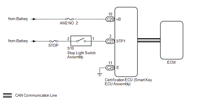
WIRING DIAGRAM
CAUTION / NOTICE / HINT
HINT:
Check the connector connection to the terminal to make sure that there is no abnormality such as a loose connection, deformation, etc.
NOTICE:
- When using the Techstream with the engine switch off, connect the Techstream to the DLC3 and turn a courtesy light switch on and off at intervals of 1.5 seconds or less until communication between the Techstream and the vehicle begins. Then select the vehicle type under manual mode and enter the following menus: Body Electrical / Smart Key. While using the Techstream, periodically turn a courtesy light switch on and off at intervals of 1.5 seconds or less to maintain communication between the Techstream and the vehicle.
- The smart key system (for Start Function) uses a multiplex communication
system (LIN communication system) and the CAN communication system. Inspect
the communication function by following How to Proceed with Troubleshooting.
Click here
.gif)
Troubleshoot the smart key system (for Start Function) after confirming that the communication systems are functioning properly.
- Before replacing the certification ECU (smart key ECU assembly), refer
to the smart key system (for Start Function) precaution (See page
).
- Inspect the fuses of circuits related to this system before performing the following inspection procedure.
- After performing repairs, perform the operation that fulfills the DTC output confirmation operation, and then confirm that no DTCs are output again.
|
DTC |
Data List Item |
Active Test Item |
|---|---|---|
|
B2284 |
Power Source Control
ABS/VSC/TRAC
|
- |
PROCEDURE
|
1. |
READ VALUE USING TECHSTREAM (STOP LIGHT SWITCH ASSEMBLY) |
(a) Connect the Techstream to the DLC3.
(b) Turn the engine switch on (IG).
(c) Turn the Techstream on.
(d) Enter the following menus: Body Electrical / Power Source Control / Data List.
(e) Read the Data List according to the display on the Techstream.
Power Source Control|
Tester Display |
Measurement Item/Range |
Normal Condition |
Specified Condition |
|---|---|---|---|
|
Stop Light Switch1 |
State of brake pedal/ON or OFF |
ON: Brake pedal depressed OFF: Brake pedal released |
|
OK:
ON (brake pedal is depressed) and OFF (brake pedal is released) appear on the screen.
| NG | .gif) |
GO TO SFI SYSTEM (HOW TO PROCEED WITH TROUBLESHOOTING) |
|
.gif)
|
2. |
CHECK HARNESS AND CONNECTOR (POWER SOURCE) |
| NG | |
REPAIR OR REPLACE HARNESS OR CONNECTOR IN CIRCUIT CONNECTED TO POWER SOURCE |
|
|
3. |
CHECK HARNESS AND CONNECTOR (GROUND) |
| NG | |
REPAIR OR REPLACE HARNESS OR CONNECTOR |
|
|
4. |
CHECK HARNESS AND CONNECTOR (CERTIFICATION ECU (SMART KEY ECU ASSEMBLY) - STOP LIGHT SWITCH ASSEMBLY) |
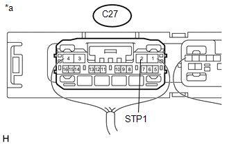
(a) Disconnect the C27 certification ECU (smart key ECU assembly) connector.
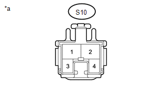
(b) Disconnect the S10 stop light switch assembly connector.
|
(c) Measure the voltage according to the value(s) in the table below. Standard Voltage:
|
|
(d) Measure the resistance according to the value(s) in the table below.
Standard Resistance:
|
Tester Connection |
Condition |
Specified Condition |
|---|---|---|
|
C27-2 (STP1) - S10-1 |
Always |
Below 1 Ω |
|
*a |
Front view of wire harness connector (to Stop Light Switch Assembly) |
| NG | |
REPAIR OR REPLACE HARNESS OR CONNECTOR |
|
|
5. |
CHECK CERTIFICATION ECU (SMART KEY ECU ASSEMBLY) |
(a) Reconnect the C27 and C29 certification ECU (smart Key ECU assembly) connectors.
(b) Reconnect the S10 stop light switch assembly connector.
|
(c) Measure the voltage according to the value(s) in the table below. Standard Voltage:
|
|
| OK | |
REPLACE CERTIFICATION ECU (SMART KEY ECU ASSEMBLY) |
| NG | |
REPLACE STOP LIGHT SWITCH ASSEMBLY |
 Lost Communication with ECM / PCM (U0100,U0140,U0142,U0155,U1117)
DESCRIPTION
These DTCs are stored when there is a CAN communication malfunction between the
certification ECU (smart key ECU assembly), ECM, main body ECU (multiplex network
body ECU) or combinat ...
 Steering Lock Position Signal Circuit Malfunction (B2285)
DESCRIPTION
This DTC is stored when the steering lock position signal sent by the steering
lock ECU (steering lock actuator or upr bracket assembly) via direct line and the
steering lock position ...
Other materials:
Removal
REMOVAL
CAUTION / NOTICE / HINT
Text in Illustration
*a
Object Exceeding Weight Limit of Transmission Jack
Be sure to perform this procedure with several people as the rear differential
carrier assembly is very heavy.
Be sure to follow the procedure ...
Installation
INSTALLATION
PROCEDURE
1. INSTALL TRANSMISSION WIRE
(a) Coat 2 new O-rings with ATF, and install them to the 2 temperature sensors.
(b) Coat a new O-ring with ATF, and install it to the transmission wire.
(c) Install the transmission wire to the automatic transmission case sub-assembly
with t ...
Four Wheel Drive (4WD) Low Switch Circuit Range / Performance (P2772)
DESCRIPTION
This DTC is output when a malfunction in the L4 detection switch is detected.
DTC No.
Detection Item
DTC Detection Condition
Trouble Area
P2772
Four Wheel Drive (4WD) Low Switch Circuit Range / Performance
...
