Toyota Tacoma (2015-2018) Service Manual: Steering Lock Position Signal Circuit Malfunction (B2285)
DESCRIPTION
This DTC is stored when the steering lock position signal sent by the steering lock ECU (steering lock actuator or upr bracket assembly) via direct line and the steering lock position signal sent via LIN communication do not match.
HINT:
When the cable is disconnected and reconnected to the negative (-) battery terminal, the power source mode returns to the state it was in before the cable was disconnected.
|
DTC Code |
DTC Detection Condition |
Trouble Area |
DTC Output Confirmation Operation |
|---|---|---|---|
|
B2285 |
The steering lock position signal sent by the steering lock ECU (steering lock actuator or upr bracket assembly) via direct line and the steering lock position signal sent via LIN communication (1-trip detection logic*) do not match. |
|
Disconnect the cable from the negative (-) battery terminal, wait 30 seconds and then reconnect the cable to the negative (-) battery terminal. Wait 40 seconds or more with the engine switch off (with the steering wheel locked), then turn the engine switch on (ACC) (with the steering unlocked) and wait 40 seconds or more. |
- *: Only detected while a malfunction is present and the engine switch is on (IG)
|
Vehicle Condition when Malfunction Detected |
Fail-safe Function when Malfunction Detected |
|---|---|
|
The engine cannot be started. |
The ECU does not send an engine start request. |
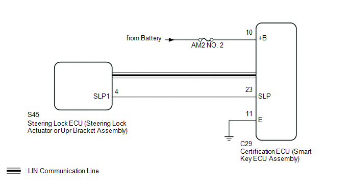
WIRING DIAGRAM
CAUTION / NOTICE / HINT
NOTICE:
- When using the Techstream with the engine switch off, connect the Techstream to the DLC3 and turn a courtesy light switch on and off at intervals of 1.5 seconds or less until communication between the Techstream and the vehicle begins. Then select the vehicle type under manual mode and enter the following menus: Body Electrical / Smart Key. While using the Techstream, periodically turn a courtesy light switch on and off at intervals of 1.5 seconds or less to maintain communication between the Techstream and the vehicle.
- The smart key system (for Start Function) uses a multiplex communication
system (LIN communication system) and the CAN communication system. Inspect
the communication function by following How to Proceed with Troubleshooting.
Click here
.gif)
Troubleshoot the smart key system (for Start Function) after confirming that the communication systems are functioning properly.
- Before replacing the certification ECU (smart key ECU assembly) or steering
lock ECU (steering lock actuator or upr bracket assembly), refer to the
smart key system (for Start Function) precaution (See page
).
- Inspect the fuses of circuits related to this system before performing the following inspection procedure.
- After performing repairs, perform the operation that fulfills the DTC output confirmation operation, and then confirm that no DTCs are output again.
|
DTC |
Data List Item |
Active Test Item |
|---|---|---|
|
B2285 |
Power Source Control Steering Unlock Switch Smart Key
|
- |
PROCEDURE
|
1. |
CHECK FOR DTC (LIN COMMUNICATION SYSTEM) |
(a) Check for DTCs (See page ).
OK:
LIN communication system DTC B2785 is not output simultaneously.
HINT:
- If the steering wheel cannot be locked or unlocked, the engine switch cannot be turned on (IG) and the engine cannot be started.
- If LIN communication is not available, the steering wheel cannot be locked or unlocked.
| NG | .gif) |
GO TO DTC B2785 |
|
.gif)
|
2. |
READ VALUE USING TECHSTREAM (STEERING UNLOCK SWITCH) |
(a) Connect the Techstream to the DLC3.
(b) Turn the engine switch on (IG).
(c) Turn the Techstream on.
(d) Enter the following menus: Body Electrical / Power Source Control / Data List.
(e) According to the display on the Techstream, read the Data List.
Power Source Control|
Tester Display |
Measurement Item/Range |
Normal Condition |
Diagnostic Note |
|---|---|---|---|
|
Steering Unlock Switch |
State of steering unlock sensor signal output from steering lock actuator assembly/ON or OFF |
ON: Steering unlocked OFF: Steering locked |
|
|
Result |
Proceed to |
|---|---|
|
Data List item does not change |
A |
|
Data List item changes |
B |
| B | |
REPLACE STEERING LOCK ECU (STEERING LOCK ACTUATOR OR UPR BRACKET ASSEMBLY) |
|
|
3. |
CHECK HARNESS AND CONNECTOR (POWER SOURCE) |
| NG | |
REPAIR OR REPLACE HARNESS OR CONNECTOR IN CIRCUIT CONNECTED TO POWER SOURCE |
|
|
4. |
CHECK HARNESS AND CONNECTOR (GROUND) |
| NG | |
REPAIR OR REPLACE HARNESS OR CONNECTOR |
|
|
5. |
INSPECT STEERING LOCK ECU (STEERING LOCK ACTUATOR OR UPPER BRACKET ASSEMBLY) |
|
(a) Measure the resistance according to the value(s) in the table below. Standard Resistance:
HINT:
|
|
| NG | |
REPLACE STEERING LOCK ECU (STEERING LOCK ACTUATOR OR UPR BRACKET ASSEMBLY) |
|
|
6. |
CHECK HARNESS AND CONNECTOR (CERTIFICATION ECU (SMART KEY ECU ASSEMBLY) - STEERING LOCK ECU (STEERING LOCK ACTUATOR OR UPR BRACKET ASSEMBLY)) |
(a) Disconnect the C29 certification ECU (smart key ECU assembly) connector.
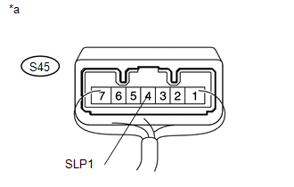
(b) Disconnect the S45 steering lock ECU (steering lock actuator or upr bracket assembly) connector.
(c) Measure the resistance according to the value(s) in the table below.
Standard Resistance:
|
Tester Connection |
Condition |
Specified Condition |
|---|---|---|
|
C29-23 (SLP) - S45-4 (SLP1) |
Always |
Below 1 Ω |
|
C29-23 (SLP) or S45-4 (SLP1) - Body ground |
Always |
10 kΩ or higher |
| OK | |
REPLACE CERTIFICATION ECU (SMART KEY ECU ASSEMBLY) |
| NG | |
REPAIR OR REPLACE HARNESS OR CONNECTOR |
 Brake Signal Malfunction (B2284)
DESCRIPTION
This DTC is stored when the brake signal sent via direct line and the brake signal
sent via CAN communication do not match.
HINT:
When the cable is disconnected and reconnected to the ...
 Detecting Vehicle Submersion (B2277)
DESCRIPTION
This DTC is stored when a malfunction in the water submersion detection circuit
in the certification ECU (smart key ECU assembly) is detected.
HINT:
When the cable is disconnected and ...
Other materials:
Removal
REMOVAL
PROCEDURE
1. PRECAUTION
NOTICE:
After turning the ignition switch off, waiting time may be required before disconnecting
the cable from the negative (-) battery terminal. Therefore, make sure to read the
disconnecting the cable from the negative (-) battery terminal notices before pr ...
Entry Exterior Alarm and Answer-back Buzzer do not Sound
DESCRIPTION
The smart key system (for Entry Function) uses the wireless door lock buzzer
to perform various vehicle exterior warnings. When the conditions of each warning
are met, the certification ECU (smart key ECU assembly) sends a buzzer activation
request signal to the main body ECU (mul ...
Parts Location
PARTS LOCATION
ILLUSTRATION
ILLUSTRATION
ILLUSTRATION
ILLUSTRATION
...
