Toyota Tacoma (2015-2018) Service Manual: Inspection
INSPECTION
PROCEDURE
1. INSPECT AIR CONDITIONING CONTROL ASSEMBLY
|
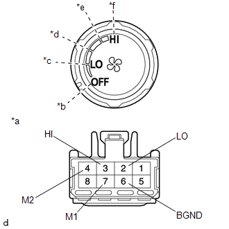
(a) Check the blower switch resistance. (1) Measure the resistance according to the value(s) in the table below. Text in Illustration
Standard Resistance:
If the result is not as specified, replace the air conditioning control assembly. |
|
|
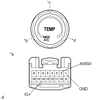
(b) Check the operation. (1) Apply battery voltage across terminals 14 (IG+) and 1 (GND). (2) Connect the positive (+) tester probe of a voltmeter to terminal 2 (AMSW) and negative (-) tester probe to terminal 1 (GND), then check the voltage. Text in Illustration
Standard Voltage:
If the result is not as specified, replace the air conditioning control assembly. |
|
|
(c) Check the operation. (1) Apply battery voltage across terminals 14 (IG+) and 1 (GND). (2) Connect the positive (+) tester probe of a voltmeter to terminal 3 (MSET) and negative (-) tester probe to terminal 1 (GND), then check the voltage. Text in Illustration
Standard Voltage:
If the result is not as specified, replace the air conditioning control assembly. |
|
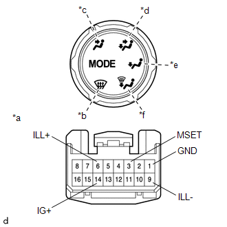
(d) Inspect the illumination.
(1) Connect the positive (+) lead to terminal 6 (ILL+) and negative (-) lead to terminal 9 (ILL-), and check that the illuminations comes on.
OK:
Illuminations comes on.
If the result is not as specified, replace the air conditioning control assembly.
 Components
COMPONENTS
ILLUSTRATION
*A
w/o Navigation System
*B
w/ Navigation System
*C
for Double Cab
*D
for Acce ...
 Installation
INSTALLATION
PROCEDURE
1. INSTALL TRANSFER POSITION SWITCH (for 4WD)
Click here
2. INSTALL ENGINE SWITCH
Click here
3. INSTALL AIR CONDITIONING CONTROL ASSEMBLY
(a) Connect the connectors.
...
Other materials:
Adjustment
ADJUSTMENT
PROCEDURE
1. PREPARE VEHICLE FOR FOG LIGHT AIMING ADJUSTMENT
(a) Prepare the vehicle:
HINT:
Ensure that there is no damage or deformation to the body around the
fog lights.
Fill the fuel tank.
Make sure that the oil is filled to the specified level.
Make sure ...
Check For Intermittent Problems
CHECK FOR INTERMITTENT PROBLEMS
1. DESCRIPTION
HINT:
A momentary interruption (open circuit) in the connectors and/or wire harness
between the sensors and ECUs can be detected through the ECU data monitor function
of the Techstream.
(a) Turn the ignition switch off.
(b) Connect the Techstre ...
Freeze Frame Data
FREEZE FRAME DATA
1. FREEZE FRAME DATA
(a) When a DTC is stored, the 4 wheel drive control ECU stores the current vehicle
state as Freeze Frame Data.
HINT:
Freeze Frame Data at the time a DTC is stored:
When the 4 wheel drive control ECU stores data at the time a DTC is stored, no
updates w ...
