Toyota Tacoma (2015-2018) Service Manual: Ambient Temperature Sensor
Components
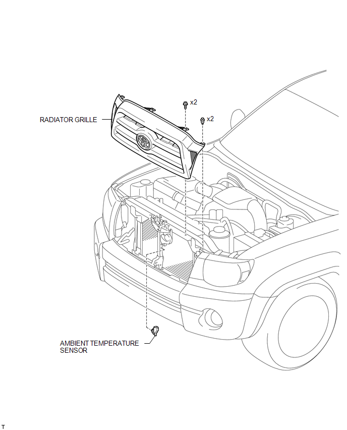
COMPONENTS
ILLUSTRATION
Inspection
INSPECTION
PROCEDURE
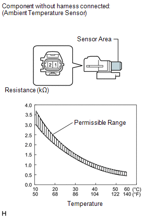
1. INSPECT AMBIENT TEMPERATURE SENSOR
|
(a) Measure the resistance according to the value(s) in the table below. Standard resistance:
NOTICE:
HINT: As the temperature increases, the resistance decreases (see the graph). If the resistance is not as specified, replace the ambient temperature sensor. |
|
Removal
REMOVAL
PROCEDURE
1. REMOVE RADIATOR GRILLE
.gif)
2. REMOVE AMBIENT TEMPERATURE SENSOR
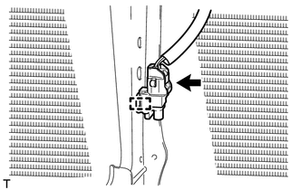
(a) Disengage the harness clamp.
(b) Disconnect the connector and remove the ambient temperature sensor.
Installation
INSTALLATION
PROCEDURE
1. INSTALL AMBIENT TEMPERATURE SENSOR
.png)
(a) Engage the harness clamp and install the ambient temperature sensor.
(b) Connect the connector.
2. INSTALL RADIATOR GRILLE
.gif)
 Air Outlet Control Servo Motor
Inspection
INSPECTION
PROCEDURE
1. INSPECT MODE CONTROL SERVO MOTOR
(a) Inspect the servo motor operation.
(1) When 12V is applied between terminals 4 (IGN) and 1 (GND), and 0V
...
 Blower Motor Controller
Components
COMPONENTS
ILLUSTRATION
Removal
REMOVAL
PROCEDURE
1. REMOVE LOWER NO. 2 INSTRUMENT PANEL AIRBAG ASSEMBLY
(See page )
2. REMOVE INSTRUMENT LOWER PANEL ASSEMBLY
3. REMOVE ...
Other materials:
Key information
The following keys are provided with the vehicle.
Vehicles without engine immobilizer
system
Master keys
Key number plate
Vehicles with engine immobilizer
system
Master keys
Key number plate
■Key number plate
Keep the plate in a safe place such as your wallet, not in the v ...
Disassembly
DISASSEMBLY
PROCEDURE
1. REMOVE STEERING GEAR OUTLET RETURN TUBE
(a) Using a union nut wrench, remove the steering gear outlet return tube.
2. REMOVE STEERING TURN PRESSURE TUBE
(a) Using a union nut wrench, remove the 2 pressure tubes.
(b) Remove the 4 O-rings from the pressure tubes.
3. ...
Removal
REMOVAL
PROCEDURE
1. REMOVE CLUTCH MASTER CYLINDER ASSEMBLY
(See page )
2. REMOVE TURN OVER SPRING SEAT COMPRESSION SPRING
(a) Remove the compression spring.
3. REMOVE CLUTCH PEDAL SUB-ASSEMBLY
(a) Remove the bolt and nut.
...
