Toyota Tacoma (2015-2018) Service Manual: Blower Motor Controller
Components
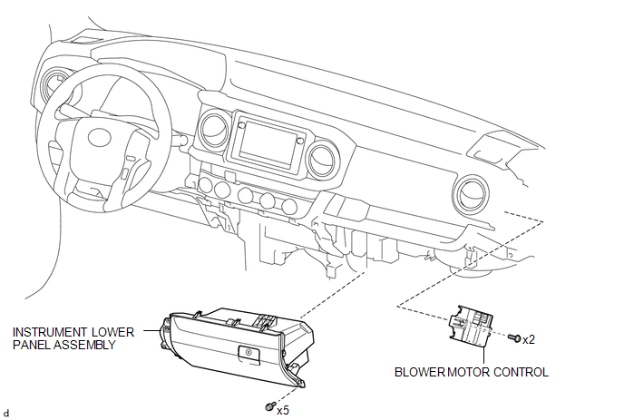
COMPONENTS
ILLUSTRATION
Removal
REMOVAL
PROCEDURE
1. REMOVE LOWER NO. 2 INSTRUMENT PANEL AIRBAG ASSEMBLY
(See page .gif) )
)
2. REMOVE INSTRUMENT LOWER PANEL ASSEMBLY
3. REMOVE ECM (for 2TR-FE)
(See page )
4. REMOVE ECM (for 2GR-FKS)
(See page )
5. REMOVE BLOWER MOTOR CONTROL
|
(a) Disconnect the 2 connectors. |
|
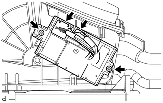
(b) Remove the 2 screws and blower motor control.
Installation
INSTALLATION
PROCEDURE
1. INSTALL BLOWER MOTOR CONTROL
(a) Install the blower motor control with the 2 screws.
(b) Connect the 2 connectors.
2. INSTALL ECM (for 2GR-FKS)
(See page .gif) )
)
3. INSTALL ECM (for 2TR-FE)
(See page )
4. INSTALL INSTRUMENT LOWER PANEL ASSEMBLY
5. INSTALL LOWER NO. 2 INSTRUMENT PANEL AIRBAG ASSEMBLY
(See page )
 Ambient Temperature Sensor
Components
COMPONENTS
ILLUSTRATION
Inspection
INSPECTION
PROCEDURE
1. INSPECT AMBIENT TEMPERATURE SENSOR
(a) Measure the resistance according to the value(s) in the table below ...
 Compressor
...
Other materials:
Inspection
INSPECTION
PROCEDURE
1. INSPECT MAGNET STARTER SWITCH ASSEMBLY
(a) Inspect the pull-in coil.
(1) Measure the resistance according to the value(s) in the table below.
Text in Illustration
*a
Terminal 50
*b
...
Panel Switches do not Function
PROCEDURE
1.
CHECK PANEL SWITCH
(a) Check for foreign matter around the switches that might prevent operation.
OK:
No foreign matter is found.
NG
REMOVE ANY FOREIGN MATTER FOUND
OK
...
Components
COMPONENTS
ILLUSTRATION
ILLUSTRATION
ILLUSTRATION
ILLUSTRATION
...
