Toyota Tacoma (2015-2018) Service Manual: Air Outlet Control Servo Motor
Inspection
INSPECTION
PROCEDURE
1. INSPECT MODE CONTROL SERVO MOTOR
|
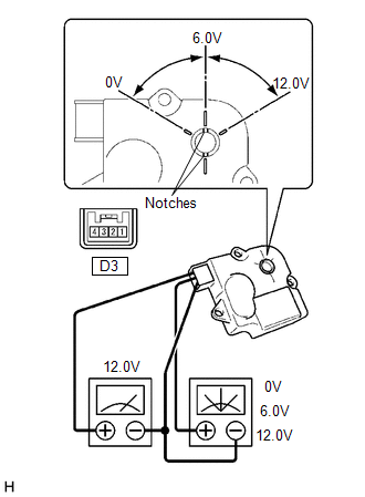
(a) Inspect the servo motor operation. (1) When 12V is applied between terminals 4 (IGN) and 1 (GND), and 0V is applied between terminals 2 (SIG) and 1 (GND), check that the line connecting the 2 notches moves to the 0V position. If the result is not as specified, replace the mode control servo motor. (2) When 12V is applied between terminals 4 (IGN) and 1 (GND), and 6V is applied between terminals 2 (SIG) and 1 (GND), check that the line connecting the 2 notches moves to the 6V position. If the result is not as specified, replace the mode control servo motor. (3) When 12V is applied between terminals 4 (IGN) and 1 (GND), and between terminals 2 (SIG) and 1 (GND), check that the line connecting the 2 notches moves to the 12V position. If the result is not as specified, replace the mode control servo motor. |
|
 Air Mix Control Servo Motor
Inspection
INSPECTION
PROCEDURE
1. INSPECT AIR MIX CONTROL SERVO MOTOR (for Manual Air Conditioning System)
(a) Inspect the servo motor operation.
Text in Illustration
...
 Ambient Temperature Sensor
Components
COMPONENTS
ILLUSTRATION
Inspection
INSPECTION
PROCEDURE
1. INSPECT AMBIENT TEMPERATURE SENSOR
(a) Measure the resistance according to the value(s) in the table below ...
Other materials:
Customize Parameters
CUSTOMIZE PARAMETERS
PROCEDURE
1. CUSTOMIZE POWER WINDOW CONTROL SYSTEM
HINT:
The following items can be customized.
NOTICE:
When the customer requests a change in a function, first make sure that
the function can be customized.
Record the current settings before customizing.
...
Pressure Control Solenoid "C" Performance (Shift Solenoid Valve SL3) (P0796)
SYSTEM DESCRIPTION
The ECM uses the vehicle speed signal and signals from the transmission revolution
sensors (NT, SP2) to detect the actual gear (1st, 2nd, 3rd, 4th, 5th or 6th gear).
The ECM compares the actual gear with the shift schedule in the ECM memory to
detect mechanical problems of t ...
Symbols used in illustrations
The symbol of a circle with a slash
through it means ŌĆ£Do notŌĆØ, ŌĆ£Do not do thisŌĆØ, or ŌĆ£Do not let this happenŌĆØ.
Arrows indicating operations
Indicates the action (pushing, turning,
etc.) used to operate switches and other devices.
Indicates the outcome of an operation
(e.g. a ...
