Toyota Tacoma (2015-2018) Service Manual: Short to GND in Outer Mirror Indicator(Master) (C1AB2)
DESCRIPTION
This DTC is stored when the blind spot monitor sensor LH detects a ground short in the blind spot monitor indicator LH.
|
DTC Code |
DTC Detection Condition |
Trouble Area |
|---|---|---|
|
C1AB2 |
With the blind spot monitor main switch assembly (warning canceling switch assembly) on, the voltage output from the blind spot monitor sensor to the indicator is low for a certain amount of time. |
|
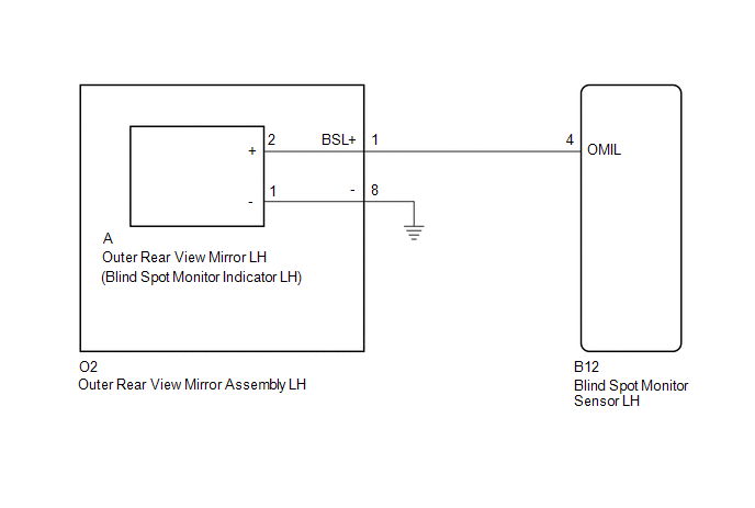
WIRING DIAGRAM
CAUTION / NOTICE / HINT
NOTICE:
When checking for DTCs, make sure that the blind spot monitor main switch assembly (warning canceling switch assembly) is on.
PROCEDURE
|
1. |
CHECK DTC |
(a) Clear the DTCs (See page .gif) ).
).
(b) Recheck for DTCs and check if the same DTC is output again (See page
).
OK:
No DTCs are output.
| OK | .gif) |
USE SIMULATION METHOD TO CHECK |
|
.gif)
|
2. |
CHECK HARNESS AND CONNECTOR (OUTER REAR VIEW MIRROR ASSEMBLY LH - BLIND SPOT MONITOR SENSOR LH) |
(a) Disconnect the O2 outer rear view mirror assembly LH connector.
(b) Disconnect the B12 blind spot monitor sensor LH connector.
(c) Measure the resistance according to the value(s) in the table below.
Standard Resistance:
|
Tester Connection |
Condition |
Specified Condition |
|---|---|---|
|
O2-1 (BSL+) - Body ground |
Always |
10 kΩ or higher |
| NG | |
REPAIR OR REPLACE HARNESS OR CONNECTOR |
|
|
3. |
CHECK HARNESS AND CONNECTOR (BLIND SPOT MONITOR SENSOR LH - OUTER REAR VIEW MIRROR LH) |
(a) Reconnect the O2 outer rear view mirror assembly LH connector.
|
(b) Disconnect the blind spot monitor sensor LH connector. |
|
(c) Disconnect the A outer rear view mirror LH connector.
(d) Measure the resistance according to the value(s) in the table below.
Standard Resistance:
|
Tester Connection |
Condition |
Specified Condition |
|---|---|---|
|
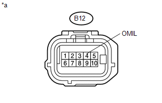
B12-4 (OMIL) - Body ground |
Always |
10 kΩ or higher |
|
*a |
Front view of wire harness connector (to Blind Spot Monitor Sensor LH) |
| NG | |
REPLACE OUTER REAR VIEW MIRROR ASSEMBLY LH |
|
|
4. |
CHECK OUTER REAR VIEW MIRROR LH |
(a) Replace the outer rear view mirror LH with a new or normally functioning
one (See page ).
(b) Clear the DTCs (See page ).
(c) Check for DTCs and check if the same DTC is output again (See page
).
OK:
No DTCs are output.
| OK | |
END (OUTER REAR VIEW MIRROR LH WAS DEFECTIVE) |
| NG | |
REPLACE BLIND SPOT MONITOR SENSOR LH |
 Open in Outer Mirror Indicator(Master) (C1AB4)
DESCRIPTION
This DTC is stored when the blind spot monitor sensor LH detects an open in the
blind spot monitor indicator LH.
DTC Code
DTC Detection Condition
Troub ...
 Short to GND in Outer Mirror Indicator(Slave) (C1AB3)
DESCRIPTION
This DTC is stored when the blind spot monitor sensor RH detects a ground short
in the blind spot monitor indicator RH.
DTC Code
DTC Detection Condition
...
Other materials:
Power Source Mode does not Change to ON (ACC)
DESCRIPTION
If the engine switch is pressed with the electrical key transmitter sub-assembly
in the cabin, the certification ECU (smart key ECU assembly) receives a signal and
changes the power source mode.
HINT:
When the cable is disconnected and reconnected to the negative (-) battery termi ...
Tailgate
The tailgate can be opened.
Pull the handle
Open the tailgate slowly
The support cables will hold the tailgate horizontal.
After closing the tailgate, try pulling it toward you to make sure it is securely
locked.
Removing the tailgate
■ Before removing the tailgate (vehicles with r ...
Cruise Main Indicator Light Circuit
DESCRIPTION
When the ECM detects a cruise control switch on signal from the cruise
control switch, the ECM sends the signal to the combination meter assembly
through CAN communication. Then the cruise control indicator light turns
on.
The cruise control indicator light circui ...
