Toyota Tacoma (2015-2018) Service Manual: Air Mix Control Servo Motor
Inspection
INSPECTION
PROCEDURE
1. INSPECT AIR MIX CONTROL SERVO MOTOR (for Manual Air Conditioning System)
|
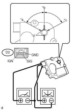
(a) Inspect the servo motor operation. Text in Illustration
(1) When 12 V is applied between terminals 4 (IGN) and 1 (GND), and 0 V is applied between terminals 2 (SIG) and 1 (GND), check that the line connecting the 2 notches moves to the 0 V position. If the result is not as specified, replace the air mix control servo motor. (2) When 12 V is applied between terminals 4 (IGN) and 1 (GND), and 6 V is applied between terminals 2 (SIG) and 1 (GND), check that the line connecting the 2 notches moves to the 6 V position. If the result is not as specified, replace the air mix control servo motor. (3) When 12 V is applied between terminals 4 (IGN) and 1 (GND), and between terminals 2 (SIG) and 1 (GND), check that the line connecting the 2 notches moves to the 12 V position. If the result is not as specified, replace the air mix control servo motor. |
|
2. INSPECT AIR MIX CONTROL SERVO MOTOR (for Automatic Air Conditioning System)
|
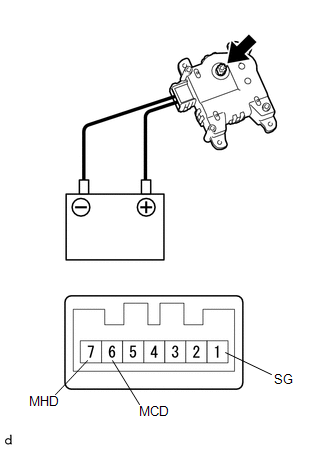
(a) Inspect the servo motor operation. (1) Connect the positive (+) lead from the battery to terminal 7 (MHD) and negative (-) lead to terminals 1 (SG), then check that the shaft rotates clockwise smoothly. (2) Connect the positive (+) lead from the battery to terminal 6 (MCD) and negative (-) lead to terminal 1 (SG) then check that the shaft rotates counterclockwise smoothly. If the operations are not as specified, replace the air mix control servo motor. |
|
 Air Inlet Control Servo Motor
Inspection
INSPECTION
PROCEDURE
1. INSPECT AIR INLET CONTROL SERVO MOTOR
(a) Inspect the servo motor operation.
(1) Connect the positive (+) lead from the battery to terminal 1 (FR ...
 Air Outlet Control Servo Motor
Inspection
INSPECTION
PROCEDURE
1. INSPECT MODE CONTROL SERVO MOTOR
(a) Inspect the servo motor operation.
(1) When 12V is applied between terminals 4 (IGN) and 1 (GND), and 0V
...
Other materials:
Installation
INSTALLATION
PROCEDURE
1. INSTALL CLUTCH DISC ASSEMBLY
(a) Insert SST into the clutch disc assembly, and then install SST and the clutch
disc assembly together to the flywheel sub-assembly.
Text in Illustration
Flywheel Sub-assembly Side
SST: 09301-00220
NOTICE ...
Transfer L4 Position Switch Circuit (C1268)
DESCRIPTION
A-TRAC is activated if wheel skid is detected while the transfer is in the L4
position.
DTC Code
DTC Detecting Condition
Trouble Areas
C1268
L4 detection switch signal input to skid control ECU (master cylinder
solenoid ...
Removal
REMOVAL
CAUTION / NOTICE / HINT
NOTICE:
Replace the blind spot monitor sensor if it has been dropped or subjected to
a severe impact.
PROCEDURE
1. REMOVE REAR BUMPER ASSEMBLY (w/ Towing Package)
(See page )
2. REMOVE REAR BUMPER ASSEMBLY (w/o Towing Package)
(See page )
3. REMOVE CONN ...
