Toyota Tacoma (2015-2018) Service Manual: Installation
INSTALLATION
PROCEDURE
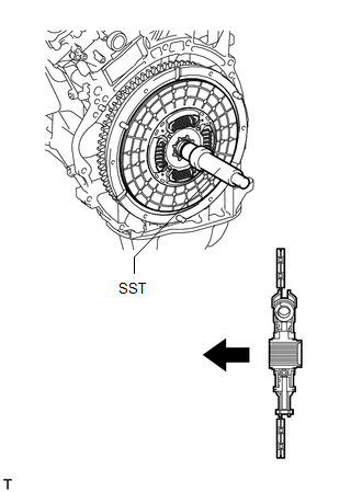
1. INSTALL CLUTCH DISC ASSEMBLY
(a) Insert SST into the clutch disc assembly, and then install SST and the clutch disc assembly together to the flywheel sub-assembly.
 Text in Illustration
.png) |
Flywheel Sub-assembly Side |
SST: 09301-00220
NOTICE:
Be sure to install the clutch disc assembly so that it is facing in the correct direction.
2. INSTALL CLUTCH COVER ASSEMBLY
|
(a) Align the matchmarks on the clutch cover assembly with the one on the flywheel sub-assembly. Text in Illustration
|
|
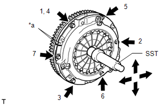
(b) Following the order shown in the illustration, tighten the 6 bolts, starting with the bolt located near the knock pin at the top.
SST: 09301-00220
Torque:
19 N·m {195 kgf·cm, 14 ft·lbf}
HINT:
- Following the order in the illustration, tighten the bolts evenly one at a time.
- Move SST up and down, and right and left lightly after checking that the clutch disc assembly is in the center, and then tighten the bolts.
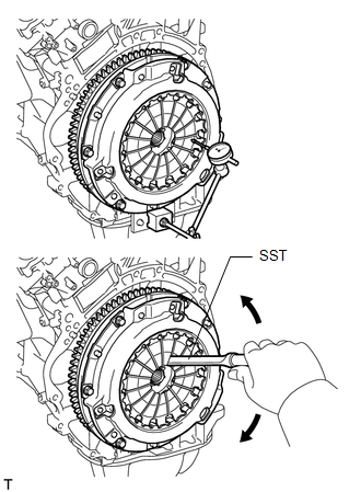
3. INSPECT AND ADJUST CLUTCH COVER ASSEMBLY
|
(a) Using a dial indicator with a roller instrument, check the diaphragm spring tip alignment. SST: 09333-00013 Maximum non-alignment: 0.5 mm (0.0196 in.) If the alignment is more than the maximum, use SST to adjust the diaphragm spring tip alignment. |
|
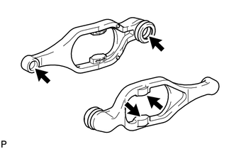
4. INSTALL CLUTCH RELEASE FORK SUB-ASSEMBLY
(a) Install the clutch release fork dust seal to the clutch release fork sub-assembly.
(b) Install the clutch release fork collar to the clutch release fork sub-assembly.
(c) Apply release hub grease to the clutch release fork sub-assembly, clutch release bearing assembly, push rod contact point and pivot points shown in the illustration.
 Text in Illustration
|
|
Release hub grease |
Grease:
Toyota Genuine Release Hub Grease or equivalent
(d) Apply clutch spline grease to the input shaft spline.
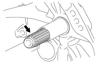 Text in Illustration
|
|
Clutch spline grease |
Grease:
Toyota Genuine Clutch Spline Grease or equivalent
(e) Install the clutch release bearing assembly to the clutch release fork sub-assembly with the clip.
(f) Install the release fork support to the manual transmission assembly.
Torque:
47 N·m {480 kgf·cm, 35 ft·lbf}
(g) Install the clutch release fork sub-assembly with the clutch release bearing assembly to the manual transmission assembly.
HINT:
After installation, move the clutch release fork sub-assembly back and forth to check that the clutch release bearing assembly slides smoothly.
5. INSTALL MANUAL TRANSMISSION ASSEMBLY
(See page .gif) )
)
 Removal
REMOVAL
PROCEDURE
1. REMOVE MANUAL TRANSMISSION ASSEMBLY
(See page )
2. REMOVE CLUTCH RELEASE FORK SUB-ASSEMBLY
(a) Remove the clutch release fork sub-assembly with the clutch releas ...
 Cruise Control
...
Other materials:
ECU Power Source Circuit
WIRING DIAGRAM
CAUTION / NOTICE / HINT
NOTICE:
Inspect the fuses for circuits related to this system before performing the following
inspection procedure.
PROCEDURE
1.
INSPECT BATTERY
(a) Check the battery voltage.
Standard voltage:
11 to 14 V
NG
...
Disposal
DISPOSAL
CAUTION / NOTICE / HINT
CAUTION:
Before performing pre-disposal deployment of any SRS part, review and closely
follow all applicable environmental and hazardous material regulations. Predisposal
deployment may be considered hazardous material treatment.
PROCEDURE
1. PRECAUTION
...
Installation
INSTALLATION
CAUTION / NOTICE / HINT
NOTICE:
When replacing the windshield glass of a vehicle equipped with a forward recognition
camera, make sure to use a Toyota genuine part. If a non-Toyota genuine part is
used, the forward recognition camera may not be able to be installed due to a missi ...
