Toyota Tacoma (2015-2018) Service Manual: Air Conditioning Amplifier Communication Stop Mode
DESCRIPTION
|
Detection Item |
Symptom |
Trouble Area |
|---|---|---|
|
Air Conditioning Amplifier Communication Stop Mode |
Either condition is met:
|
|
WIRING DIAGRAM
CAUTION / NOTICE / HINT
CAUTION:
When performing the confirmation driving pattern, obey all speed limits and traffic laws.
NOTICE:
- Because the order of diagnosis is important to allow correct diagnosis,
make sure to begin troubleshooting using How to Proceed with Troubleshooting
when CAN communication system related DTCs are output.
Click here
.gif)
- Before measuring the resistance of the CAN bus, turn the ignition switch off and leave the vehicle for 1 minute or more without operating the key or any switches, or opening or closing the doors. After that, disconnect the cable from the negative (-) battery terminal and leave the vehicle for 1 minute or more before measuring the resistance.
- After turning the ignition switch off, waiting time may be required
before disconnecting the cable from the negative (-) battery terminal. Therefore,
make sure to read the disconnecting the cable from the negative (-) battery
terminal notices before proceeding with work.
Click here
- Some parts must be initialized and set when replacing or removing and
installing parts.
Click here
- After performing repairs, perform the DTC check procedure and confirm
that the DTCs are not output again.
DTC check procedure: Turn the ignition switch to ON and wait for 1 minute or more. Then operate the suspected malfunctioning system and drive the vehicle at 60 km/h (37 mph) or more for 5 minutes or more.
- After the repair, perform the CAN bus check and check that all the ECUs
and sensors connected to the CAN communication system are displayed as normal.
Click here
- Inspect the fuses for circuits related to this system before performing the following procedure.
HINT:
- Before disconnecting related connectors for inspection, push in on each connector body to check that the connector is not loose or disconnected.
- When a connector is disconnected, check that the terminals and connector body are not cracked, deformed or corroded.
PROCEDURE
|
1. |
SYSTEM CHECK |
(a) Check the vehicle specifications.
Result|
Result |
Proceed to |
|---|---|
|
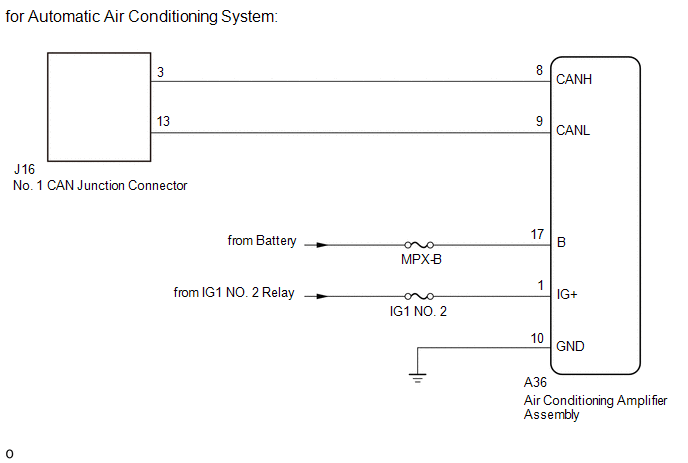
for Automatic Air Conditioning System |
A |
|
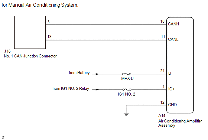
for Manual Air Conditioning System |
B |
| B | .gif) |
GO TO STEP 4 |
|
.gif)
|
2. |
CHECK FOR OPEN IN CAN BUS LINES (AIR CONDITIONING AMPLIFIER ASSEMBLY BRANCH LINE) |
(a) Disconnect the cable from the negative (-) battery terminal.
|
(b) Disconnect the air conditioning amplifier assembly connector. |
|
(c) Measure the resistance according to the value(s) in the table below.
Standard Resistance:
|
Tester Connection |
Condition |
Specified Condition |
|---|---|---|
|
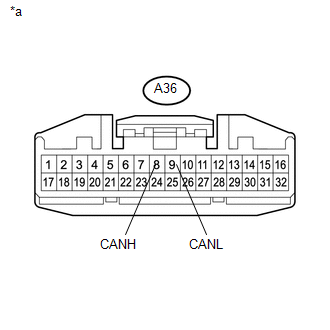
A36-8 (CANH) - A36-9 (CANL) |
Cable disconnected from negative (-) battery terminal |
54 to 69 Ω |
|
*a |
Front view of wire harness connector (to Air Conditioning Amplifier Assembly) |
| NG | |
REPAIR OR REPLACE CAN BRANCH LINE OR CONNECTOR (AIR CONDITIONING AMPLIFIER ASSEMBLY) |
|
|
3. |
CHECK HARNESS AND CONNECTOR (POWER SOURCE CIRCUIT) |
|
(a) Measure the resistance according to the value(s) in the table below. Standard Resistance:
|
|
(b) Connect the cable to the negative (-) battery terminal.
(c) Measure the voltage according to the value(s) in the table below.
Standard Voltage:
|
Tester Connection |
Switch Condition |
Specified Condition |
|---|---|---|
|
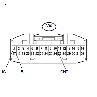
A36-1 (IG+) - Body ground |
Ignition switch ON |
11 to 14 V |
|
A36-17 (B) - Body ground |
Always |
11 to 14 V |
|
*a |
Front view of wire harness connector (to Air Conditioning Amplifier Assembly) |
| OK | |
REPLACE AIR CONDITIONING AMPLIFIER ASSEMBLY |
| NG | |
REPAIR OR REPLACE HARNESS OR CONNECTOR (POWER SOURCE CIRCUIT) |
|
4. |
CHECK FOR OPEN IN CAN BUS LINES (AIR CONDITIONING AMPLIFIER ASSEMBLY BRANCH LINE) |
(a) Disconnect the cable from the negative (-) battery terminal.
|
(b) Disconnect the air conditioning amplifier assembly connector. |
|
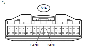
(c) Measure the resistance according to the value(s) in the table below.
Standard Resistance:
|
Tester Connection |
Condition |
Specified Condition |
|---|---|---|
|
A14-10 (CANH) - A14-11 (CANL) |
Cable disconnected from negative (-) battery terminal |
54 to 69 Ω |
|
*a |
Front view of wire harness connector (to Air Conditioning Amplifier Assembly) |
| NG | |
REPAIR OR REPLACE CAN BRANCH LINE OR CONNECTOR (AIR CONDITIONING AMPLIFIER ASSEMBLY) |
|
|
5. |
CHECK HARNESS AND CONNECTOR (POWER SOURCE CIRCUIT) |
|
(a) Measure the resistance according to the value(s) in the table below. Standard Resistance:
|
|
(b) Connect the cable to the negative (-) battery terminal.
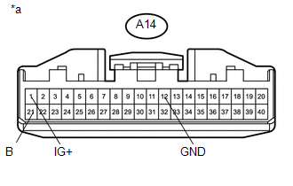
(c) Measure the voltage according to the value(s) in the table below.
Standard Voltage:
|
Tester Connection |
Switch Condition |
Specified Condition |
|---|---|---|
|
A14-1 (IG+) - Body ground |
Ignition switch ON |
11 to 14 V |
|
A14-21 (B) - Body ground |
Always |
11 to 14 V |
|
*a |
Front view of wire harness connector (to Air Conditioning Amplifier Assembly) |
| OK | |
REPLACE AIR CONDITIONING AMPLIFIER ASSEMBLY |
| NG | |
REPAIR OR REPLACE HARNESS OR CONNECTOR (POWER SOURCE CIRCUIT) |
 Clearance Warning ECU Communication Stop Mode
DESCRIPTION
Detection Item
Symptom
Trouble Area
Clearance Warning ECU Communication Stop Mode
Either Condition is met:
Commu ...
 ECM Communication Stop Mode
DESCRIPTION
Detection Item
Symptom
Trouble Area
ECM Communication Stop Mode
Either condition is met:
Communication stop for ...
Other materials:
Front Blower Resistor
Inspection
INSPECTION
PROCEDURE
1. INSPECT BLOWER RESISTOR
(a) Check the resistance.
(1) Measure the resistance according to the value(s) in the table below.
Standard Resistance:
Tester Connection
Condition
Specified
...
Front Passenger Side Power Window does not Operate with Front Passenger Side
Power Window Switch
DESCRIPTION
When the engine is running or the ignition switch is ON, the front power window
regulator motor assembly RH is operated by the front power window regulator switch
assembly RH. The front power window regulator motor assembly RH has motor, regulator,
and ECU functions.
HINT:
If th ...
Installation
INSTALLATION
PROCEDURE
1. INSTALL HEADLIGHT DIMMER SWITCH ASSEMBLY
(a) Engage the 3 claws to install the headlight dimmer switch assembly.
(b) Connect the connector.
2. INSTALL WINDSHIELD WIPER SWITCH ASSEMBLY
3. INSTALL SPIRAL CABLE WITH SENSOR SUB-ASSEMBLY
(See page ) ...
