Toyota Tacoma (2015-2018) Service Manual: Clearance Warning ECU Communication Stop Mode
DESCRIPTION
|
Detection Item |
Symptom |
Trouble Area |
|---|---|---|
|
Clearance Warning ECU Communication Stop Mode |
Either Condition is met:
|
|
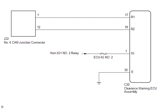
WIRING DIAGRAM
CAUTION / NOTICE / HINT
CAUTION:
When performing the confirmation driving pattern, obey all speed limits and traffic laws.
NOTICE:
- Because the order of diagnosis is important to allow correct diagnosis,
make sure to begin troubleshooting using How to Proceed with Troubleshooting
when CAN communication system related DTCs are output.
Click here
.gif)
- Before measuring the resistance of the CAN bus, turn the ignition switch off and leave the vehicle for 1 minute or more without operating the key or any switches, or opening or closing the doors. After that, disconnect the cable from the negative (-) battery terminal and leave the vehicle for 1 minute or more before measuring the resistance.
- After turning the ignition switch off, waiting time may be required
before disconnecting the cable from the negative (-) battery terminal. Therefore,
make sure to read the disconnecting the cable from the negative (-) battery
terminal notices before proceeding with work.
Click here
- Some parts must be initialized and set when replacing or removing and
installing parts.
Click here
- After performing repairs, perform the DTC check procedure and confirm
that the DTCs are not output again.
DTC check procedure: Turn the ignition switch to ON and wait for 1 minute or more. Then operate the suspected malfunctioning system and drive the vehicle at 60 km/h (37 mph) or more for 5 minutes or more.
- After the repair, perform the CAN bus check and check that all the ECUs
and sensors connected to the CAN communication system are displayed as normal.
Click here
- Inspect the fuses for circuits related to this system before performing the following procedure.
HINT:
- Before disconnecting related connectors for inspection, push in on each connector body to check that the connector is not loose or disconnected.
- When a connector is disconnected, check that the terminals and connector body are not cracked, deformed or corroded.
PROCEDURE
|
1. |
CHECK FOR OPEN IN CAN BUS LINES (CLEARANCE WARNING ECU ASSEMBLY CAN BRANCH LINE) |
|
(a) Disconnect the cable from the negative (-) battery terminal. |
|
(b) Disconnect the clearance warning ECU assembly connector.
(c) Measure the resistance according to the value(s) in the table below.
Standard Resistance:
|
Tester Connection |
Condition |
Specified Condition |
|---|---|---|
|
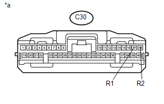
C30-17 (R1) - C30-18 (R2) |
Cable disconnected from negative (-) battery terminal |
54 to 69 Ω |
|
*a |
Front view of wire harness connector (to Clearance Warning ECU Assembly) |
| NG | .gif) |
REPAIR OR REPLACE CAN BRANCH LINES OR CONNECTOR (CLEARANCE WARNING ECU ASSEMBLY) |
|
.gif)
|
2. |
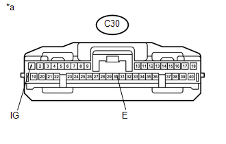
CHECK HARNESS AND CONNECTOR (POWER SOURCE CIRCUIT) |
|
(a) Measure the resistance according to the value(s) in the table below. Standard Resistance:
|
|
(b) Connect the cable to the negative (-) battery terminal.
(c) Measure the voltage according to the value(s) in the table below.
Standard Voltage:
|
Tester Connection |
Switch Condition |
Specified Condition |
|---|---|---|
|
C30-1 (IG) - Body ground |
Ignition switch ON |
11 to 14 V |
|
*a |
Front view of wire harness connector (to Clearance Warning ECU Assembly) |
| OK | |
REPLACE CLEARANCE WARNING ECU ASSEMBLY |
| NG | |
REPAIR OR REPLACE HARNESS OR CONNECTOR |
 ECU Malfunction (B1003)
DESCRIPTION
DTC No.
DTC Detection Condition
Trouble Area
B1003
A malfunction in the non-volatile storage of the central gateway ECU
(n ...
 Air Conditioning Amplifier Communication Stop Mode
DESCRIPTION
Detection Item
Symptom
Trouble Area
Air Conditioning Amplifier Communication Stop Mode
Either condition is met:
...
Other materials:
Customize Parameters
CUSTOMIZE PARAMETERS
NOTICE:
When the customer requests a change in a function, first make sure that
the function can be customized.
Make a note of the current settings before customizing.
HINT:
The following PCS functions and the pre-collision system sensitivity setting
...
Motor Power Supply Voltage Circuit (C142B-C146D)
DESCRIPTION
The motor relay and motor fail-safe relay are built into the brake actuator assembly.
During ABS, TRAC, VSC, or brake assist operation, the skid control ECU (brake
actuator assembly) turns on the motor relay to run the pump motor in the brake actuator
assembly.
When a motor system ...
Removal
REMOVAL
PROCEDURE
1. REMOVE SHIFT LEVER KNOB SUB-ASSEMBLY (for Automatic Transmission)
(a) Using a molding remover A, disengage the 2 claws to separate the
shifting hole cover sub-assembly.
(b) Rotate the shift lever knob sub-as ...
