Toyota Tacoma (2015-2018) Service Manual: Rear Seat Inner Belt Assembly(for Access Cab)
Components
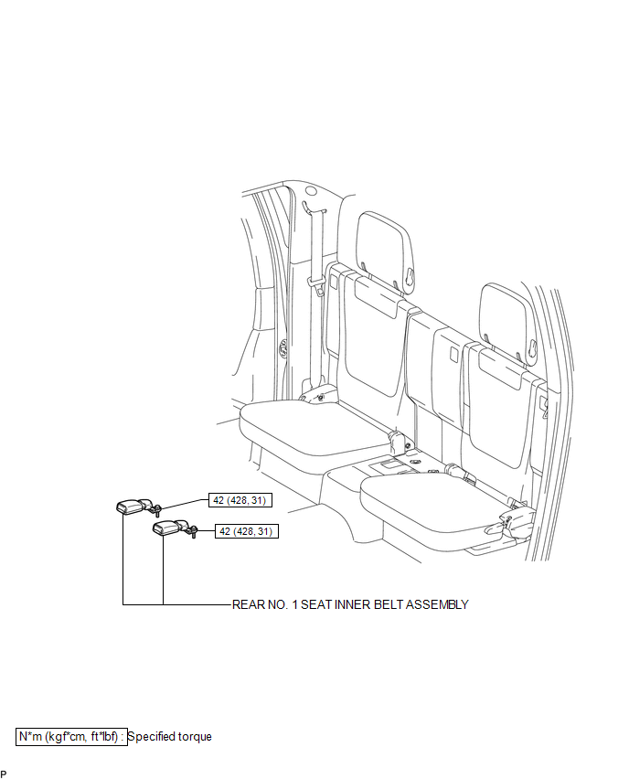
COMPONENTS
ILLUSTRATION
Removal
REMOVAL
PROCEDURE
1. REMOVE REAR NO. 1 SEAT INNER BELT ASSEMBLY
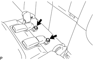
(a) Open the 2 anchor covers.
|
(b) Loosen the 2 bolts to remove the 2 rear No. 1 seat inner belt assemblies. |
|
Installation
INSTALLATION
PROCEDURE
1. INSTALL REAR NO. 1 SEAT INNER BELT ASSEMBLY
(a) Tighten the 2 bolts to install the 2 rear No. 1 seat inner belt assemblies.
Torque:
42 N·m {428 kgf·cm, 31 ft·lbf}
(b) Check that the floor anchor rotates smoothly.
(c) Close the 2 anchor covers.
 Rear Center Seat Outer Belt Assembly(for Double Cab)
Components
COMPONENTS
ILLUSTRATION
Removal
REMOVAL
PROCEDURE
1. REMOVE REAR SEATBACK HINGE COVER
2. REMOVE REAR SEATBACK BOARD SUB-ASSEMBLY
3. REMOVE SEAT BELT ANCHOR COVER CAP
...
 Rear Seat Inner Belt Assembly(for Double Cab)
Installation
INSTALLATION
PROCEDURE
1. INSTALL REAR SEAT INNER BELT ASSEMBLY
(a) for LH Side:
(1) Install the rear seat inner belt assembly with the bolt.
Text in Illustration
...
Other materials:
Wireless Charger Assembly
Components
COMPONENTS
ILLUSTRATION
Removal
REMOVAL
PROCEDURE
1. REMOVE FRONT CONSOLE BOX
(See page
)
2. REMOVE MOBILE WIRELESS CHARGER CRADLE ASSEMBLY
(a) Remove the 5 screws and mobile wireless charger cradle assembly.
Install ...
On-vehicle Inspection
ON-VEHICLE INSPECTION
PROCEDURE
1. INSPECT DRIVE BELT
(a) Visually check the belt for defects, such as excessive wear and frayed cords.
If any defects are found, replace the drive belt.
HINT:
Replace the belt if there are any missing ribs.
2. BLEED POWER STEERING SYSTEM
(a) Check the fluid ...
Pressure Control Solenoid "B" Actuator Stuck Off (P07757F)
SYSTEM DESCRIPTION
The ECM uses the vehicle speed signal and signals from the transmission revolution
sensors (NT, SP2) to detect the actual gear (1st, 2nd, 3rd, 4th, 5th or 6th gear).
The ECM compares the actual gear with the shift schedule in the ECM memory to
detect mechanical problems of t ...
