Toyota Tacoma (2015-2018) Service Manual: Cargo Light Switch
Components
COMPONENTS
ILLUSTRATION
Inspection
INSPECTION
PROCEDURE
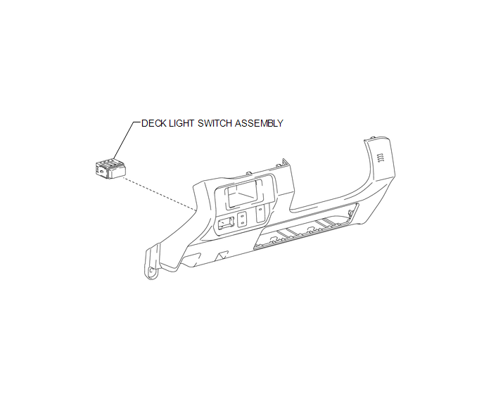
1. INSPECT DECK LIGHT SWITCH ASSEMBLY
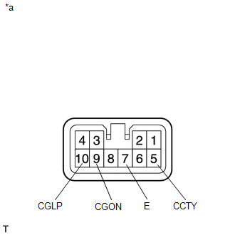
(a) Check the resistance.
|
(1) Measure the resistance according to the value(s) in the table below. Text in Illustration
Standard Resistance:
If the result is not as specified, replace the deck light switch assembly. |
|
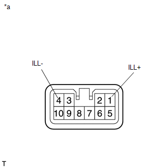
(b) Check the illumination.
|
(1) Apply battery voltage to the connector and check the illumination condition. Text in Illustration
OK:
If the result is not as specified, replace the deck light switch assembly. |
|
Installation
INSTALLATION
PROCEDURE
1. INSTALL DECK LIGHT SWITCH ASSEMBLY
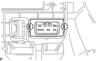
(a) Engage the 2 claws to install the deck light switch assembly.
2. INSTALL INSTRUMENT PANEL LOWER FINISH PANEL SUB-ASSEMBLY
(See page .gif) )
)
Removal
REMOVAL
PROCEDURE
1. REMOVE INSTRUMENT PANEL LOWER FINISH PANEL SUB-ASSEMBLY
(See page .gif) )
)
2. REMOVE DECK LIGHT SWITCH ASSEMBLY
|
(a) Disengage the 2 claws to remove the deck light switch assembly. |
|
 Cargo Light
Components
COMPONENTS
ILLUSTRATION
Removal
REMOVAL
PROCEDURE
1. REMOVE ROOF HEADLINING ASSEMBLY
for Double Cab:
(See page
)
for Access Cab:
(See page
)
...
 Daytime Running Light Relay
Inspection
INSPECTION
PROCEDURE
1. INSPECT NO. 1 DAY TIME RUNNING LIGHT RELAY
(a) Check the resistance.
(1) Measure the resistance according to the value(s) in the table below.
St ...
Other materials:
Front Stabilizer Bar
Components
COMPONENTS
ILLUSTRATION
Inspection
INSPECTION
PROCEDURE
1. INSPECT FRONT STABILIZER LINK ASSEMBLY
(a) Flip the ball joint stud back and forth 5 times, as shown in the illustration,
before installing the nut.
(b) Using a torque wrench, turn the nut continuously at a rate ...
Ambient Temperature Sensor Circuit (B1412)
DESCRIPTION
The ambient temperature sensor is installed in front of the condenser to detect
the ambient temperature which is used to control the air conditioning system AUTO
mode. This sensor is connected to the air conditioning amplifier assembly and detects
fluctuations in the ambient tempe ...
Stereo Component Amplifier Malfunction (B15A3)
DESCRIPTION
This DTC is stored when a malfunction occurs in the stereo component amplifier
assembly.
DTC No.
DTC Detection Condition
Trouble Area
B15A3
When one of the conditions below is met:
Internal power supply malfun ...
