Toyota Tacoma (2005–2015) Owners Manual: Active traction control system
The active traction control system automatically helps prevent the spinning of 4 wheels when the vehicle is started or accelerated on slippery road surfaces.
■ System operation
 Vehicles with an automatic transmission:
Stop the vehicle, shift the shift lever to N and put the frontwheel drive control
switch in the L4 position.
Vehicles with an automatic transmission:
Stop the vehicle, shift the shift lever to N and put the frontwheel drive control
switch in the L4 position.
Vehicles with a manual transmission: Stop the vehicle or reduce your speed to less than 2 mph (3 km/h). Depress the clutch pedal and put the front-wheel drive control switch in the L4 position.
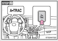
Press the A-TRAC switch to activate the system.
At this time, the active traction control system indicator will come on.
To cancel the system, push the switch again.
When the active traction control system is operating
If four wheels spin, the slip indicator flashes to indicate that the active traction control system has been engaged.
■When the rear differential is locked (vehicles with the rear differential lock system)
The active traction control system is activated only when the vehicle speed is less than 3 mph (6 km/h).
■Sounds and vibrations caused by the active traction control system
●A sound may be heard from the engine compartment when the engine is started or just after the vehicle begins to move. This sound does not indicate that a malfunction has occurred in the system.
●Vibrations may be felt through the vehicle body and steering. It may occur when the system is operating.
■If the brake system overheats
The system will cease operation, a buzzer will sound and A-TRAC indicator blink to alert the driver. Stop the vehicle in a safe place. (There is no problem with continuing normal driving.) The system will be automatically restored after a short time.
CAUTION
■The active traction control system may not operate effectively when
Directional control and power may not be achievable while driving on slippery road surfaces, even if the active traction control system is operating.
Do not drive the vehicle in conditions where stability and power may be lost.
 Four-wheel drive system
Use the front-wheel drive control switch to select the following transfer modes.
H2 (high speed position, two-wheel
drive)
Use this for normal driving on dry hard-surfaced roads.
This position ...
 AUTO LSD system
The AUTO LSD system aids traction by using the traction control system to control
engine performance and braking when one of the rear wheels begins to spin.
The system should be used only when one ...
Other materials:
Air Outlet Control Servo Motor
Inspection
INSPECTION
PROCEDURE
1. INSPECT MODE CONTROL SERVO MOTOR
(a) Inspect the servo motor operation.
(1) When 12V is applied between terminals 4 (IGN) and 1 (GND), and 0V
is applied between terminals 2 (SIG) and 1 (GND), check that the line connecting
the 2 notches ...
Road Test
ROAD TEST
1. PROBLEM SYMPTOM CONFIRMATION
(a) Based on the result of the customer problem analysis, try to reproduce the
symptoms. If the problem is that the transmission does not shift up or down, or
that the shift point is too high or too low, conduct the following road test referring
to t ...
Pressure Sensor or Switch (C1254)
DESCRIPTION
The accumulator pressure sensor is connected to the skid control ECU in the master
cylinder solenoid.
DTC No.
DTC Detecting Condition
Trouble Areas
C1254
Accumulator pressure sensor fault
(Fluid pressure does not chang ...
