Toyota Tacoma (2015-2018) Service Manual: ECU Power Source Circuit
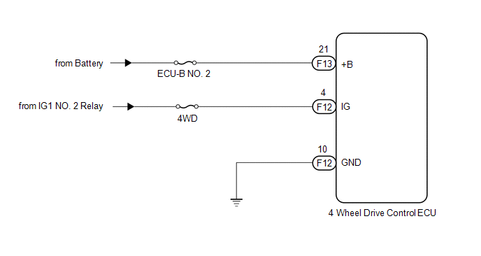
WIRING DIAGRAM
CAUTION / NOTICE / HINT
NOTICE:
Inspect the fuses for circuits related to this system before performing the following inspection procedure.
PROCEDURE
|
1. |
INSPECT BATTERY |
(a) Check the battery voltage.
Standard voltage:
11 to 14 V
| NG | .gif) |
CHECK OR REPLACE CHARGING SYSTEM OR BATTERY |
|
.gif)
|
2. |
CHECK HARNESS AND CONNECTOR (+B AND IG TERMINAL) |
(a) Turn the ignition switch off.
|
(b) Disconnect the 4 wheel drive control ECU connector. |
|
(c) Measure the voltage according to the value(s) in the table below.
Standard Voltage:
|
Tester Connection |
Switch Condition |
Specified Condition |
|---|---|---|
|
F13-21 (+B) - Body ground |
Always |
11 to 14 V |
|
F12-4 (IG) - Body ground |
Ignition switch ON |
11 to 14 V |
|
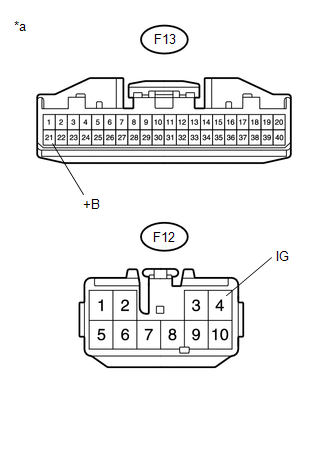
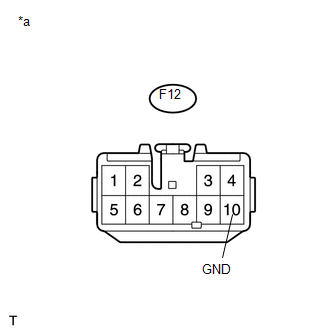
*a |
Front view of wire harness connector (to 4 Wheel Drive Control ECU) |
| NG | |
REPAIR OR REPLACE HARNESS OR CONNECTOR (+B OR IG CIRCUIT) |
|
|
3. |
CHECK HARNESS AND CONNECTOR (GND TERMINAL) |
(a) Turn the ignition switch off.
(b) Disconnect the 4 wheel drive control ECU connector.
|
(c) Measure the resistance according to the value(s) in the table below. Standard Resistance:
|
|
| OK | |
PROCEED TO NEXT SUSPECTED AREA SHOWN IN PROBLEM SYMPTOMS TABLE |
| NG | |
REPAIR OR REPLACE HARNESS OR CONNECTOR (GND CIRCUIT) |
 4WD ECU Malfunction (P163B)
DESCRIPTION
This DTC is output when a malfunction is detected in the 4 wheel drive control
ECU internal circuit.
DTC No.
Detection Item
DTC Detection Condition
...
 Lock Switch Circuit
WIRING DIAGRAM
PROCEDURE
1.
CHECK REAR DIFFERENTIAL LOCK INDICATOR LIGHT
(a) Turn the ignition switch to ON.
(b) for 4WD:
Finish switching to L4.
(c) Check the ...
Other materials:
Precaution
PRECAUTION
1. BASIC REPAIR HINT
(a) HINTS ON OPERATIONS
1
Attire
Always wear a clean uniform.
A hat and safety shoes must be worn.
2
Vehicle protection
Prepare a grille cover, fe ...
Reassembly
REASSEMBLY
PROCEDURE
1. INSTALL UPPER RADIATOR TANK
(a) Install a new upper radiator tank.
Text in Illustration
*1
Upper Radiator Tank
*2
Core Plate
*a
Correc ...
Unable to Lock Steering Wheel
DESCRIPTION
The steering lock actuator assembly activates the steering lock motor and moves
the lock bar into the steering column to lock the steering.
When the steering lock is operating, the steering may not lock when the lock
bar is not aligned with the lock hole of the steering column. In ...
