Toyota Tacoma (2015-2018) Service Manual: Wireless Charger Assembly
Components
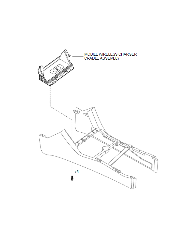
COMPONENTS
ILLUSTRATION
Removal
REMOVAL
PROCEDURE
1. REMOVE FRONT CONSOLE BOX
(See page .gif) )
)
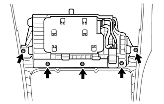
2. REMOVE MOBILE WIRELESS CHARGER CRADLE ASSEMBLY
|
(a) Remove the 5 screws and mobile wireless charger cradle assembly. |
|
Installation
INSTALLATION
PROCEDURE
1. INSTALL MOBILE WIRELESS CHARGER CRADLE ASSEMBLY
(a) Install the mobile wireless charger cradle assembly with the 5 screws.
2. INSTALL FRONT CONSOLE BOX
(See page .gif) )
)
 Voltage Inverter
Components
COMPONENTS
ILLUSTRATION
Inspection
INSPECTION
PROCEDURE
1. INSPECT VOLTAGE INVERTER ASSEMBLY
(a) Check the voltage inverter assembly.
(1) Measure the voltage according to the ...
 Wireless Charger Main Switch
Components
COMPONENTS
ILLUSTRATION
Removal
REMOVAL
PROCEDURE
1. REMOVE INSTRUMENT PANEL LOWER CENTER FINISH PANEL
(See page )
2. REMOVE MOBILE WIRELESS CHARGER SWITCH
(a) Di ...
Other materials:
Data List / Active Test
DATA LIST / ACTIVE TEST
1. ACTIVE TEST
HINT:
Using the Techstream to perform Active Tests allows relays, VSVs, actuators and
other items to be operated without removing any parts. This non-intrusive functional
inspection can be very useful because intermittent operation may be discovered befo ...
Precaution
PRECAUTION
1. EXPRESSIONS OF IGNITION SWITCH
HINT:
The type of ignition switch used on this model differs according to the specifications
of the vehicle. The expressions listed in the table below are used in this section.
Expression
Ignition Switch
(Position)
...
Transmission Fluid Temperature Sensor "B" Circuit Short to Ground (P274011)
DESCRIPTION
The No. 2 ATF temperature sensor is installed in the transmission valve body
assembly.
If the ECM detects an abnormally high ATF temperature near this sensor, it illuminates
the warning indicator.
HINT:
The temperature of ATF easily rises when towing, climbing hills, in
...
