Toyota Tacoma (2015-2018) Service Manual: Wireless Charger Main Switch
Components
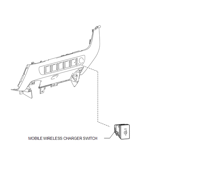
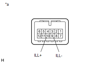
COMPONENTS
ILLUSTRATION
Removal
REMOVAL
PROCEDURE
1. REMOVE INSTRUMENT PANEL LOWER CENTER FINISH PANEL
(See page .gif) )
)
2. REMOVE MOBILE WIRELESS CHARGER SWITCH
|
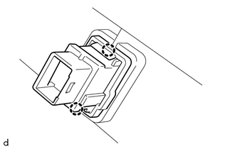
(a) Disengage the 2 claws to remove the mobile wireless charger switch. |
|
Inspection
INSPECTION
PROCEDURE
1. INSPECT MOBILE WIRELESS CHARGER SWITCH
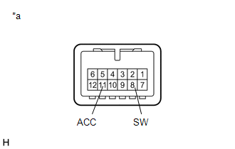
(a) Check the mobile wireless charger switch.
|
(1) Measure the resistance according to the value(s) in the table below. Standard Resistance:
If the result is not as specified, replace the mobile wireless charger switch. |
|
(b) Check that the switch indicator light illuminates.
|
(1) Apply battery voltage to the mobile wireless charger switch connector and check the operation of the switch indicator light. OK:
If the result is not as specified, replace the mobile wireless charger switch. |
|
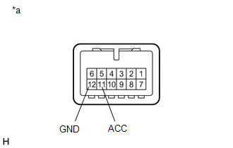
(c) Check that the switch illuminates.
|
(1) Apply battery voltage to the mobile wireless charger switch and check that the switch illuminates. OK:
If the result is not as specified, replace the mobile wireless charger switch. |
|
Installation
INSTALLATION
PROCEDURE
1. INSTALL MOBILE WIRELESS CHARGER SWITCH
(a) Engage the 2 claws to install the mobile wireless charger switch.
2. INSTALL INSTRUMENT PANEL LOWER CENTER FINISH PANEL
(See page .gif) )
)
 Wireless Charger Assembly
Components
COMPONENTS
ILLUSTRATION
Removal
REMOVAL
PROCEDURE
1. REMOVE FRONT CONSOLE BOX
(See page
)
2. REMOVE MOBILE WIRELESS CHARGER CRADLE ASSEMBLY
(a) Remove the 5 sc ...

Other materials:
Open / Short in Steering Lock ECU (B2781)
DESCRIPTION
The steering lock ECU and steering lock motor are built into the steering lock
actuator assembly.
The steering lock ECU (steering lock actuator or UPR bracket assembly) detects
whether the steering lock is in the lock or unlock position by using the lock sensor
and unlock sensor ...
Before Starting Adjustment
BEFORE STARTING ADJUSTMENT
CAUTION / NOTICE / HINT
NOTICE:
When replacing the windshield glass of a vehicle equipped with a forward recognition
camera, make sure to use a Toyota genuine part. If a non-Toyota genuine part is
used, the forward recognition camera may not be able to be installed ...
IG Power Source Circuit
DESCRIPTION
The main power source is supplied to the air conditioning amplifier assembly
when the ignition switch is turned to ON.
The power is used for operating the air conditioning amplifier assembly, servo
motors, etc.
WIRING DIAGRAM
CAUTION / NOTICE / HINT
NOTICE:
Inspect the fuses ...
