Toyota Tacoma (2015-2018) Service Manual: Adjustment
ADJUSTMENT
CAUTION / NOTICE / HINT
HINT:
- Use the same procedures for both the LH and RH sides.
- The procedure described below is for the LH side.
- Centering bolts are used to mount the door hinge to the vehicle body and door. The door cannot be adjusted with the centering bolts on. Substitute the centering bolts for standard bolts when making adjustments.
- A bolt without a torque specification is shown in the standard bolt
chart (See page
.gif) ).
).
PROCEDURE
1. INSPECT FRONT DOOR PANEL SUB-ASSEMBLY (for Double Cab)
(a) Check that the clearance measurements of areas "A" through "J" are within each standard range.
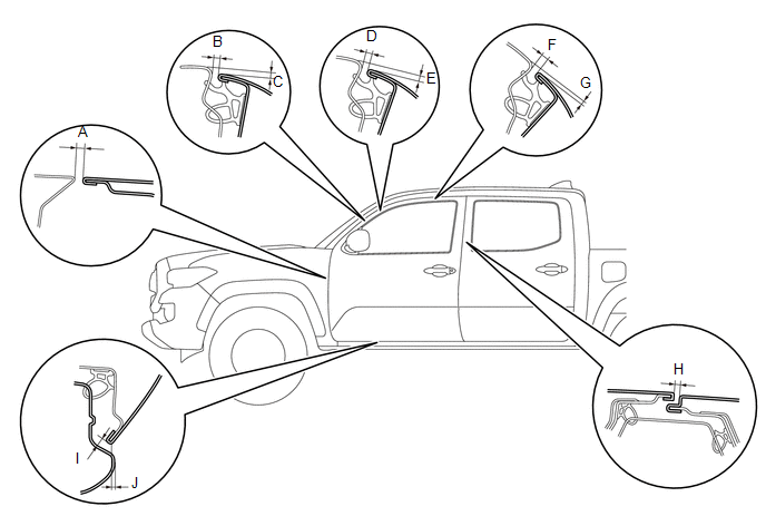 Standard:
|
Area |
Measurement |
Area |
Measurement |
|
A |
3.2 to 6.2 mm (0.126 to 0.244 in.) |
B |
3.4 to 6.4 mm (0.134 to 0.252 in.) |
|
C |
1.1 to 4.1 mm (0.043 to 0.161 in.) |
D |
3.3 to 6.3 mm (0.130 to 0.248 in.) |
|
E |
1.1 to 4.1 mm (0.043 to 0.161 in.) |
F |
3.3 to 6.3 mm (0.130 to 0.248 in.) |
|
G |
0.7 to 3.7 mm (0.028 to 0.146 in.) |
H |
3.5 to 6.5 mm (0.138 to 0.256 in.) |
|
I |
3.5 to 6.5 mm (0.138 to 0.256 in.) |
J |
0.5 to 3.5 mm (0.020 to 0.138 in.) |
2. INSPECT FRONT DOOR PANEL SUB-ASSEMBLY (for Access Cab)
(a) Check that the clearance measurements of areas "A" through "J" are within each standard range.
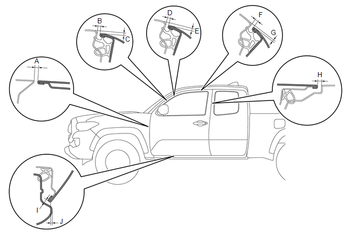 Standard:
|
Area |
Measurement |
Area |
Measurement |
|
A |
3.2 to 6.2 mm (0.126 to 0.244 in.) |
B |
3.4 to 6.4 mm (0.134 to 0.252 in.) |
|
C |
1.1 to 4.1 mm (0.043 to 0.161 in.) |
D |
3.3 to 6.3 mm (0.130 to 0.248 in.) |
|
E |
1.1 to 4.1 mm (0.043 to 0.161 in.) |
F |
3.3 to 6.3 mm (0.130 to 0.248 in.) |
|
G |
0.7 to 3.7 mm (0.028 to 0.146 in.) |
H |
4.5 to 7.5 mm (0.177 to 0.295 in.) |
|
I |
3.5 to 6.5 mm (0.138 to 0.256 in.) |
J |
0.5 to 3.5 mm (0.020 to 0.138 in.) |
3. ADJUST FRONT DOOR PANEL SUB-ASSEMBLY
(a) Apply strips of protective tape to the door panel and fender panel, as shown in the illustration.
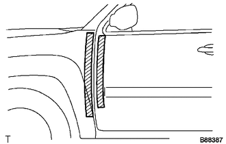 Text in Illustration
.png) |
Protective Tape |
|
(b) Open the door, and then disengage the 3 clips. HINT: If any clips are damaged, replace them with new ones. |
|
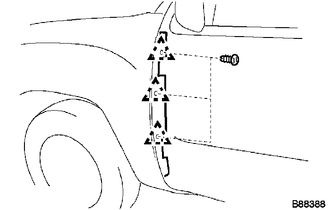
(c) Remove the front fender side panel protector LH from the gap between the fender and door.
|
(d) Using SST, adjust the door horizontally and vertically by loosening the body side hinge bolts. SST: 09812-00010 |
|
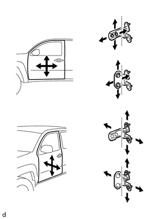
(e) Tighten the body side hinge bolts after the adjustment.
Torque:
26 N·m {265 kgf·cm, 19 ft·lbf}
(f) Horizontally and vertically adjust the door by loosening the door side hinge bolts.
(g) Tighten the door side hinge bolts after the adjustment.
Torque:
26 N·m {265 kgf·cm, 19 ft·lbf}
|
(h) Adjust the striker position by slightly loosening the striker mounting screws with a T40 "TORX" socket wrench and hitting the striker with a plastic hammer. |
|
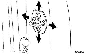
(i) Using a T40 "TORX" socket wrench, tighten the striker mounting screws after the adjustment.
Torque:
23 N·m {235 kgf·cm, 17 ft·lbf}
|
(j) Install the front fender side panel protector LH with the 3 clips. |
|
 Front Door
...
 Components
COMPONENTS
ILLUSTRATION
*1
FRONT ARMREST BASE UPPER PANEL SUB-ASSEMBLY
*2
FRONT DOOR GLASS INNER WEATHERSTRIP
*3
FRONT DOOR ...
Other materials:
Automatic transmission
Select a shift position appropriate for the driving conditions.
■ Shifting the shift lever
5-speed models
While the engine switch is on, depress
the brake pedal and move the shift lever.
4-speed models
While the engine switch is on, depress
the brake pedal and move the shift l ...
System Description
SYSTEM DESCRIPTION
1. GENERAL
(a) To assist the driver with parking the vehicle by displaying an image of the
area behind the vehicle, this system has a rear television camera assembly mounted
on the tailgate. The system displays the image on the multi-display.
(b) This system consists of the ...
Problem Symptoms Table
PROBLEM SYMPTOMS TABLE
HINT:
Use the table below to help determine the cause of problem symptoms.
If multiple suspected areas are listed, the potential causes of the symptoms
are listed in order of probability in the "Suspected Area" column of the
table. Check each sy ...
