Toyota Tacoma (2015-2018) Service Manual: Voltage Inverter
Components
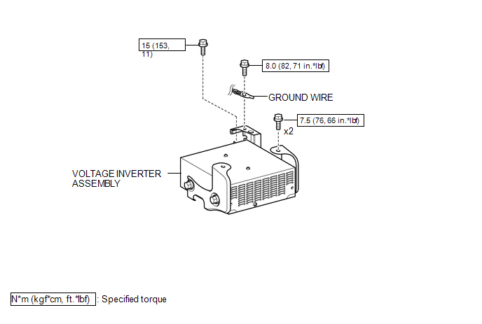
COMPONENTS
ILLUSTRATION
Inspection
INSPECTION
PROCEDURE
1. INSPECT VOLTAGE INVERTER ASSEMBLY
(a) Check the voltage inverter assembly.
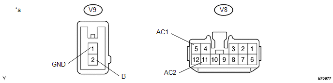
(1) Measure the voltage according to the value(s) in the table below.
 Text in Illustration
|
*a |
Component with harness connected (Voltage Inverter Assembly) |
- |
- |
Standard:
|
Tester Connection |
Switch Condition |
Specified Condition |
|---|---|---|
|
V9-2 (B) - V9-1 (GND) |
Ignition switch (ON) |
11 to 15 V |
|
V9-1 (GND) - Body ground |
Always |
Below 1 V |
|
V8-5 (AC1) - V8-11 (AC2) |
Ignition switch (ON) Main switch (ON) |
108 to 132 V |
If the result is not as specified, replace the voltage inverter assembly.
Removal
REMOVAL
PROCEDURE
1. REMOVE REAR CONSOLE BOX ASSEMBLY
(See page .gif) )
)
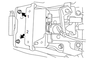
2. REMOVE VOLTAGE INVERTER ASSEMBLY
|
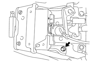
(a) Remove the bolt to disconnect the ground wire. |
|
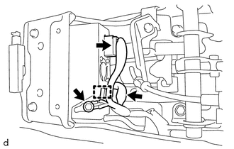
(b) Disconnect the 2 connectors and disengage the clamp.
|
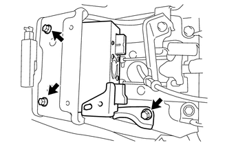
(c) Remove the 3 bolts and voltage inverter assembly. |
|
Installation
INSTALLATION
PROCEDURE
1. INSTALL VOLTAGE INVERTER ASSEMBLY
(a) Temporarily install the voltage inverter assembly with the 3 bolts.
|
(b) Tighten the 2 bolts in the order shown in the illustration. Torque: 7.5 N·m {76 kgf·cm, 66 in·lbf} |
|
|
(c) Tighten the bolt. Torque: 15 N·m {153 kgf·cm, 11 ft·lbf} |
|
(d) Connect the 2 connectors and engage the clamp.
(e) Connect the ground wire with the bolt.
Torque:
8.0 N·m {82 kgf·cm, 71 in·lbf}
2. INSTALL REAR CONSOLE BOX ASSEMBLY
(See page .gif) )
)
 Rear Power Outlet Switch
Components
COMPONENTS
ILLUSTRATION
Inspection
INSPECTION
PROCEDURE
1. INSPECT MAIN SWITCH ASSEMBLY
(a) Check the main switch assembly.
(1) Measure the resistance according to ...
 Wireless Charger Assembly
Components
COMPONENTS
ILLUSTRATION
Removal
REMOVAL
PROCEDURE
1. REMOVE FRONT CONSOLE BOX
(See page
)
2. REMOVE MOBILE WIRELESS CHARGER CRADLE ASSEMBLY
(a) Remove the 5 sc ...
Other materials:
Installation
INSTALLATION
CAUTION / NOTICE / HINT
HINT:
The following procedures are for BD20 (w/o Differential Lock).
PROCEDURE
1. INSTALL REAR DIFFERENTIAL CARRIER ASSEMBLY
(a) Clean the contact surfaces of the rear differential carrier assembly and
axle housing.
(b) Install the rear differ ...
A/C ECU Vehicle Information Reading/Writing Processor Malfunction (B15F5)
DESCRIPTION
This DTC is stored when items controlled by the Air conditioning amplifier assembly
cannot be customized via the navigation system vehicle customization screen.
HINT:
The Air conditioning amplifier assembly controls the air conditioning system
related items that are customizable v ...
Data Signal Circuit between Radio Receiver and Extension Module
DESCRIPTION
The stereo component tuner assembly sends the image data signal to the radio
and display receiver assembly via this circuit.
WIRING DIAGRAM
PROCEDURE
1.
CHECK NO. 1 NAVIGATION WIRE
(a) Disconnect the R33 radio and display receiver assembly connect ...
