Toyota Tacoma (2015-2018) Service Manual: Installation
INSTALLATION
PROCEDURE
1. SET NO. 1 CYLINDER TO TDC/COMPRESSION
.gif)
2. INSTALL CAMSHAFT TIMING GEAR BOLT
NOTICE:
There are different types of camshaft timing gear bolts. Make sure to check the identification mark to determine the tightening torque.
.png)
|
*a |
Identification Mark Stamp |
|
Item |
Identification Mark Stamp |
|
|---|---|---|
|
Intake Side |
Exhaust Side |
|
|
Type A |
A |
B |
|
Type B |
D |
G |
|
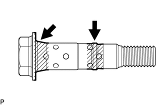
(a) Apply engine oil to the areas of the camshaft timing gear bolt shown in the illustration. |
|
(b) Temporarily install the camshaft timing gear bolt.
Torque:
10 N·m {102 kgf·cm, 7 ft·lbf}
HINT:
Make sure that the flange part of the camshaft timing gear bolt is directly contacting the camshaft timing gear assembly.
(c) Loosen the camshaft timing gear bolt 60 to 180°.
(d) Turn the crankshaft pulley assembly counterclockwise approximately 30 to 90°.
|
(e) Using SST, hold the crankshaft pulley assembly. SST: 09213-54015 91651-60855 SST: 09330-00021 |
|
.png)
(f) Tighten the camshaft timing gear bolt.
Torque:
for Type A :
120 N·m {1224 kgf·cm, 89 ft·lbf}
for Type B :
95 N·m {969 kgf·cm, 70 ft·lbf}
3. INSTALL CAMSHAFT TIMING OIL CONTROL SOLENOID ASSEMBLY
(See page )
4. INSTALL NO. 1 ENGINE UNDER COVER SUB-ASSEMBLY
Torque:
30 N·m {306 kgf·cm, 22 ft·lbf}
5. INSTALL NO. 2 ENGINE UNDER COVER SUB-ASSEMBLY (w/ Off Road Package)
Torque:
30 N·m {306 kgf·cm, 22 ft·lbf}
 Removal
REMOVAL
CAUTION / NOTICE / HINT
NOTICE:
If one of the camshaft timing gear bolts is already removed, do not remove any
other camshaft timing gear bolts.
PROCEDURE
1. REMOVE NO. 2 ENGINE UNDER C ...

Other materials:
Lost Communication with Front Camera Module (U023A)
DESCRIPTION
These DTCs are stored when the CAN communication system is malfunctioning.
DTC No.
DTC Detecting Condition
Trouble Area
U023A
Lost Communication With Image Processing Module"A"
The main body ECU ...
Radio Receiver Power Source Circuit
DESCRIPTION
This is the power source circuit to operate the navigation receiver assembly.
WIRING DIAGRAM
CAUTION / NOTICE / HINT
NOTICE:
Inspect the fuses for circuits related to this system before performing
the following inspection procedure.
PROCEDURE
1.
...
Reassembly
REASSEMBLY
PROCEDURE
1. INSTALL NO. 2 ANTENNA CORD SUB-ASSEMBLY
(a) Using hot-melt glue, install the No. 2 antenna cord sub-assembly as shown
in the illustration.
2. INSTALL NO. 1 ROOF WIRE (w/ Vanity Light)
(a) w/ EC Mirror:
(1) Align the aiming tape as shown in the illustration.
...
