Toyota Tacoma (2015-2018) Service Manual: Vacuum Warning Switch
Components
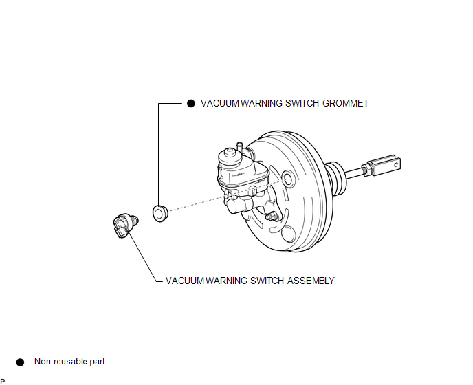
COMPONENTS
ILLUSTRATION
On-vehicle Inspection
ON-VEHICLE INSPECTION
PROCEDURE
1. INSPECT BRAKE FLUID LEVEL IN RESERVOIR
2. INSPECT BRAKE BOOSTER ASSEMBLY
.gif)
3. INSPECT VACUUM WARNING SWITCH ASSEMBLY
(a) Start the engine and stop it after 1 or 2 minutes.
(b) Disconnect the connector from the vacuum warning switch assembly.
(c) Measure the resistance of the vacuum warning switch assembly.
Standard Resistance:
10 kΩ or higher
(d) With the engine stopped, depress the brake pedal several times to release vacuum from the brake booster assembly, and measure the resistance of the vacuum warning switch assembly.
Standard Resistance:
Below 1 Ω
(e) Connect the connector to the vacuum warning switch assembly.
Installation
INSTALLATION
PROCEDURE
1. INSTALL VACUUM WARNING SWITCH GROMMET
(a) Install a new vacuum warning switch grommet to the brake booster assembly.
2. INSTALL VACUUM WARNING SWITCH ASSEMBLY
(a) Install the vacuum warning switch assembly to the brake booster assembly as shown in the illustration.
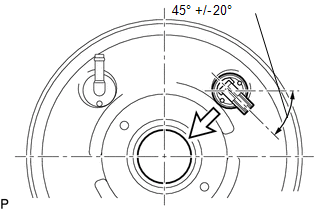 Text in Illustration
.png) |
Center of the Brake Booster Assembly |
(b) Connect the connector to the vacuum warning switch assembly.
Removal
REMOVAL
PROCEDURE
1. REMOVE VACUUM WARNING SWITCH ASSEMBLY
(a) Disconnect the connector from the vacuum warning switch assembly.
(b) Remove the vacuum warning switch assembly from the brake booster assembly.
2. REMOVE VACUUM WARNING SWITCH GROMMET
(a) Remove the vacuum warning switch grommet from the brake booster assembly.
 Vacuum Pump
Components
COMPONENTS
ILLUSTRATION
Installation
INSTALLATION
PROCEDURE
1. INSTALL VACUUM PUMP ASSEMBLY
(a) Apply engine oil to the 2 O-rings on the vacuum pump assembly.
(b) Apply engine ...

Other materials:
Open in ABS Solenoid Relay Circuit (C146E,C146F)
DESCRIPTION
The ABS solenoid relay supplies power to the ABS solenoid and TRAC solenoid.
The solenoid relay is turned on 1.5 seconds after the ignition switch is turned
ON, and is turned off if an open or short in the solenoid is detected by the self
diagnosis performed when the engine starts ...
Removal
REMOVAL
PROCEDURE
1. REMOVE NO. 1 ENGINE UNDER COVER SUB-ASSEMBLY
2. REMOVE FRONT EXHAUST PIPE ASSEMBLY
(See page )
3. REMOVE NO. 1 OIL COOLER INLET TUBE AND NO. 1 OIL COOLER OUTLET TUBE
NOTICE:
When disconnecting the hoses from the tube, support the tube by hand and be careful
to prevent ...
Fail-safe Chart
FAIL-SAFE CHART
1. FAIL-SAFE OPERATION AND DEACTIVATION CONDITION
DIFFERENTIAL SYSTEM (w/ Differential Lock)
DTC No.
Fail-safe Operation
Fail-safe Deactivation Condition
U0122
All switching prohibited
When rear differential is locked ...
