Toyota Tacoma (2015-2018) Service Manual: Removal
REMOVAL
PROCEDURE
1. REMOVE NO. 1 ENGINE UNDER COVER SUB-ASSEMBLY
2. REMOVE FRONT EXHAUST PIPE ASSEMBLY
(See page .gif) )
)
3. REMOVE NO. 1 OIL COOLER INLET TUBE AND NO. 1 OIL COOLER OUTLET TUBE
NOTICE:
When disconnecting the hoses from the tube, support the tube by hand and be careful to prevent the tube from being deformed.
HINT:
Use a container to catch any ATF.
|
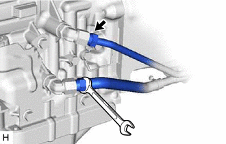
(a) Disconnect the No. 1 oil cooler inlet tube and No. 1 oil cooler outlet tube from the automatic transmission assembly. |
|
|
(b) Slide the 2 clips and disconnect the No. 1 oil cooler inlet hose and No. 1 oil cooler outlet hose from the No. 1 oil cooler inlet tube and No. 1 oil cooler outlet tube. |
|
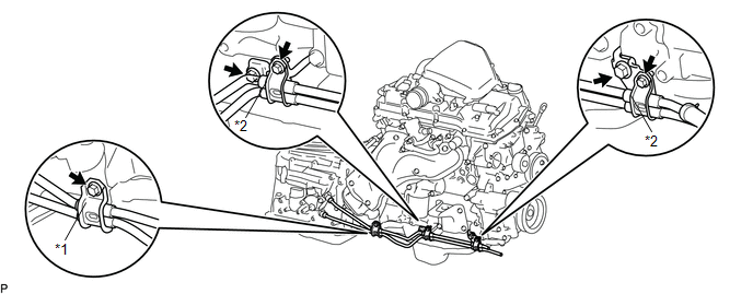
(c) Remove the bolt and flexible hose clamp from the automatic transmission assembly.
 Text in Illustration
|
*1 |
Flexible Hose Clamp |
*2 |
Oil Cooler Tube Clamp |
(d) Remove the 2 bolts to open the 2 oil cooler tube clamps and remove the No. 1 oil cooler inlet tube and No. 1 oil cooler outlet tube.
(e) Remove the 2 bolts and 2 oil cooler tube clamps from the engine assembly.
4. REMOVE NO. 1 OIL COOLER INLET HOSE AND NO. 1 OIL COOLER OUTLET HOSE
NOTICE:
When disconnecting the hoses from the tube, support the tube by hand and be careful to prevent the tube from being deformed.
HINT:
Use a container to catch any ATF.
|
(a) Slide the 2 clips and remove the No. 1 oil cooler inlet hose and No. 1 oil cooler outlet hose from the oil cooler tube. |
|
5. REMOVE NO. 4 OIL COOLER INLET HOSE AND NO. 4 OIL COOLER OUTLET HOSE
NOTICE:
When disconnecting the hoses from the tube, support the tube by hand and be careful to prevent the tube from being deformed.
HINT:
Use a container to catch any ATF.
|
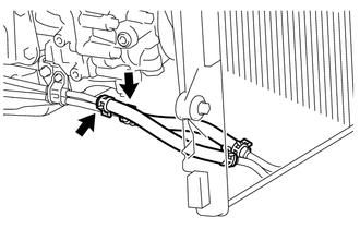
(a) Detach the claw to open the clamp. |
|
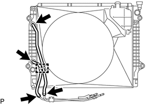
(b) Slide the 2 clips and disconnect the No. 4 oil cooler inlet hose and No. 4 oil cooler outlet hose from the oil cooler tube.
(c) Slide the 2 clips and remove the No. 4 oil cooler inlet hose and No. 4 oil cooler outlet hose from the radiator assembly.
6. REMOVE OIL COOLER TUBE
|
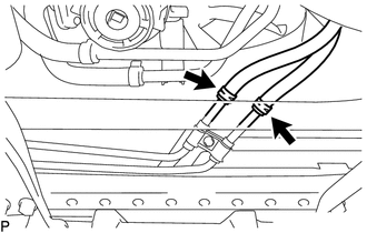
(a) Remove the 2 bolts and oil cooler tube from the vehicle body. |
|
.png)
 Installation
INSTALLATION
PROCEDURE
1. INSTALL OIL COOLER TUBE
(a) Install the oil cooler tube to the vehicle body with the 2 bolts.
Torque:
28 N·m {286 kgf·cm, 21 ft·lbf}
2. INSTALL NO. 4 OIL COOLER INL ...
 Oil Pump
...
Other materials:
Disassembly
DISASSEMBLY
PROCEDURE
1. REMOVE INTAKE VALVE
(a) Using SST, compress the inner compression spring and remove the valve
spring retainer locks.
SST: 09202-70020
SST: 09202-00021
09202-01010
09202-01020
(b) Remove the valve s ...
Power Window Switch Malfunction (B2312)
DESCRIPTION
The power window regulator motor assembly is operated by the power window regulator
master switch assembly or power window regulator switch assembly. The power window
regulator motor assembly has motor, regulator and ECU functions.
This DTC is output when the ECU built into the reg ...
Short in Front Passenger Side Squib 2nd Step Circuit (B1815/54-B1818/54)
DESCRIPTION
The front passenger side squib 2nd step circuit consists of the airbag sensor
assembly and the instrument panel passenger without door airbag assembly.
The circuit signals the SRS to deploy when airbag deployment conditions are met.
These DTCs are set when a malfunction is detected ...
