Toyota Tacoma (2015-2018) Service Manual: Vacuum Pump
Components
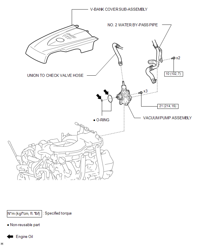
COMPONENTS
ILLUSTRATION
Installation
INSTALLATION
PROCEDURE
1. INSTALL VACUUM PUMP ASSEMBLY
(a) Apply engine oil to the 2 O-rings on the vacuum pump assembly.
(b) Apply engine oil to the inner surface of the installation hole.
(c) Install the vacuum pump assembly so that the oil pipe engages with the hole of the camshaft and the coupling teeth with the grooves on the camshaft tip.
NOTICE:
- Ensure that the vacuum pump assembly is installed securely.
- Be careful not to pinch the O-ring.
|
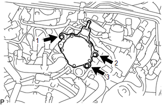
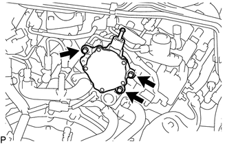
(d) Install the vacuum pump assembly to the engine assembly with the 3 bolts in the order shown in the illustration. Torque: 21 N·m {214 kgf·cm, 15 ft·lbf} NOTICE: After installation, check that there are no gaps between the matching surfaces and that the vacuum pump assembly is no installed at an angle. |
|
2. INSTALL NO. 2 WATER BY-PASS PIPE
(a) Install the No. 2 water by-pass pipe with the 2 bolts.
Torque:
10 N·m {102 kgf·cm, 7 ft·lbf}
3. CONNECT UNION TO CHECK VALVE HOSE
(a) Connect the union to check valve hose and slide the clip to secure it.
4. INSTALL V-BANK COVER SUB-ASSEMBLY
.gif)
5. INSPECT VACUUM PUMP OPERATION
On-vehicle Inspection
ON-VEHICLE INSPECTION
PROCEDURE
1. OPERATION CHECK
(a) Remove the V-bank cover sub-assembly.
(See page .gif) )
)
(b) Slide the clip and disconnect the union to check valve hose from the vacuum pump assembly.
(c) Connect the hose of the vacuum gauge to the vacuum pump assembly.
(d) Start the engine and warm it up for more than 2 minutes.
(e) With the engine idling, check the negative pressure of the vacuum pump.
Standard pressure:
More than 90.0 kPa (675 mmHg, 26.6 in.Hg)
HINT:
The vacuum pump assembly is listed as one of the 200000 km (124000 mile) maintenance parts. Make sure to disassemble and inspect it every 200000 km (124000 miles) and replace parts as necessary.
(f) Remove the vacuum gauge from the vacuum pump assembly.
(g) Connect the union to check valve hose to the vacuum pump assembly and slide the clip to secure it.
(h) Install the V-bank cover sub-assembly.
(See page )
Removal
REMOVAL
CAUTION / NOTICE / HINT
HINT:
The vacuum pump assembly is listed as one of the 200000 km (124000 mile) maintenance parts. Make sure to disassemble and inspect it every 200000 km (124000 miles) and replace parts as necessary.
PROCEDURE
1. REMOVE V-BANK COVER SUB-ASSEMBLY
.gif)
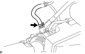
2. DISCONNECT UNION TO CHECK VALVE HOSE
|
(a) Slide the clip and disconnect the union to check valve hose. |
|
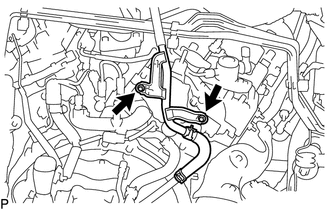
3. SEPARATE NO. 2 WATER BY-PASS PIPE
|
(a) Remove the 2 bolts and separate the No. 2 water by-pass pipe. |
|
4. REMOVE VACUUM PUMP ASSEMBLY
|
(a) Remove the 3 bolts and vacuum pump assembly from the engine assembly. HINT: If there are any oil leaks or any O-ring is damaged, replace the vacuum pump assembly with a new one. |
|
 Installation
INSTALLATION
PROCEDURE
1. INSTALL REAR BRAKE DRUM SUB-ASSEMBLY
(a) Install a new drum gasket onto the rear brake drum.
(b) Install the rear brake drum.
2. ADJUST REAR DRUM BRAKE SHOE CLEARANCE
...
 Vacuum Warning Switch
Components
COMPONENTS
ILLUSTRATION
On-vehicle Inspection
ON-VEHICLE INSPECTION
PROCEDURE
1. INSPECT BRAKE FLUID LEVEL IN RESERVOIR
2. INSPECT BRAKE BOOSTER ASSEMBLY
3. INSPECT VACUUM ...
Other materials:
Seat Position Airbag Sensor Circuit Malfunction (B1653/35)
DESCRIPTION
The seat position airbag sensor circuit consists of the airbag sensor assembly
and the seat position airbag sensor.
DTC B1653/35 is stored when a malfunction is detected in the seat position airbag
sensor assembly circuit.
DTC No.
DTC Detection Condition
...
Air Fuel Ratio Sensor
Components
COMPONENTS
ILLUSTRATION
Removal
REMOVAL
PROCEDURE
1. REMOVE AIR FUEL RATIO SENSOR (for Bank 1 Sensor 1)
(a) Disconnect the air fuel ratio sensor connector.
(b) Disengage the clamp to separate the air fuel ratio sensor wire ...
Reassembly
REASSEMBLY
PROCEDURE
1. INSTALL MASTER CYLINDER RESERVOIR GROMMET
(a) Apply lithium soap base glycol grease to 2 new grommets.
(b) Install the 2 grommets onto the brake master cylinder reservoir.
2. INSTALL BRAKE MASTER CYLINDER RESERVOIR ASSEMBLY
(a) Install the brake master cylinder reservoi ...
