Toyota Tacoma (2015-2018) Service Manual: Open in ABS Solenoid Relay Circuit (C146E,C146F)
DESCRIPTION
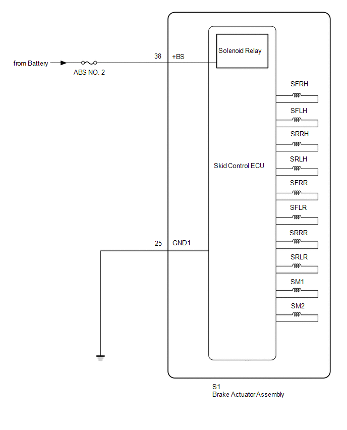
The ABS solenoid relay supplies power to the ABS solenoid and TRAC solenoid.
The solenoid relay is turned on 1.5 seconds after the ignition switch is turned ON, and is turned off if an open or short in the solenoid is detected by the self diagnosis performed when the engine starts running.
The ABS solenoid relay is housed in the skid control ECU in the actuator assembly.
|
DTC No. |
Detection Item |
DTC Detection Condition |
Trouble Area |
|---|---|---|---|
|
C146E |
Open in ABS Solenoid Relay Circuit |
Either of the following is detected:
|
|
|
C146F |
Short in ABS Solenoid Relay Circuit |
Immediately after ignition switch turned ON and solenoid relay is OFF, relay contact is ON continuously for 4.5 seconds or more. |
Skid control ECU (Brake actuator assembly) |
HINT:
DTC will be output when conditions for either of the patterns in the table above are met.
WIRING DIAGRAM
CAUTION / NOTICE / HINT
NOTICE:
- When replacing the skid control ECU (brake actuator assembly), perform
zero point calibration and store system information (See page
.gif) ).
).
- Inspect the fuses for circuits related to this system before performing the following inspection procedure.
HINT:
When C1241 and/or C1417 is output together with C146E and/or C146F, inspect and repair the trouble areas indicated by C1241 and/or C1417 first.
- for C1241: (See page )
- for C1417: (See page )
PROCEDURE
|
1. |
CHECK TERMINAL VOLTAGE (+BS TERMINAL) |
(a) Turn the ignition switch off.
(b) Make sure that there is no looseness at the locking part and the connecting part of the connectors.
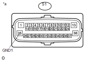
(c) Disconnect the S1 skid control ECU (brake actuator assembly) connector.
|
(d) Measure the voltage according to the value(s) in the table below. Standard Voltage:
|
|
.png)
| NG | .gif) |
REPAIR OR REPLACE HARNESS OR CONNECTOR (+BS CIRCUIT) |
|
.gif)
|
2. |
CHECK HARNESS AND CONNECTOR (GND1 TERMINAL) |
|
(a) Measure the resistance according to the value(s) in the table below. Standard Resistance:
|
|
| NG | |
REPAIR OR REPLACE HARNESS OR CONNECTOR (GND1 CIRCUIT) |
|
|
3. |
RECONFIRM DTC |
HINT:
These codes are detected when a problem is determined in the skid control ECU (brake actuator assembly).
The solenoid circuits are in the skid control ECU (brake actuator assembly).
Therefore, solenoid circuit inspection and solenoid unit inspection cannot be performed.
Be sure to check if any DTCs are output before replacing the skid control ECU (brake actuator assembly).
(a) Reconnect the S1 skid control ECU (brake actuator assembly) connector.
(b) Clear the DTCs (See page
).
(c) Turn the ignition switch off.
(d) Start the engine.
(e) Drive the vehicle at a speed of 20 km/h (12 mph) or more for 30 seconds or more.
(f) Check if the same DTC is recorded (See page
).
|
Result |
Proceed to |
|---|---|
|
DTC C146E and/or C146F are not output |
A |
|
DTC C146E and C146F are output |
B |
HINT:
- If a speed signal of 6 km/h (4 mph) or more is input to the skid control ECU (brake actuator assembly), with the ignition switch to ON and the stop light switch off, the ECU performs self diagnosis of the motor and solenoid circuits.
- If the normal system code is output (the trouble code is not output), slightly jiggle the connectors, wire harness, and fuses of the skid control ECU (brake actuator assembly). Make sure that no DTCs are output.
- If any DTCs are output while jiggling a connector or wire harness from the skid control ECU (brake actuator assembly), inspect and repair the connector or wire harness.
- The DTCs were probably output due to a bad connection of the connector terminal.
| A | |
USE SIMULATION METHOD TO CHECK |
| B | |
REPLACE BRAKE ACTUATOR ASSEMBLY |
 Unusual Bank Angle Detected (C1440)
DESCRIPTION
If the skid control ECU (brake actuator assembly) determines that the vehicle
is being driven at a steep bank angle, the skid control ECU (brake actuator assembly)
stores DTC C1440 wh ...
 Invalid Data Received from Deceleration Sensor (C1442,C1443)
DESCRIPTION
The airbag sensor assembly has a built-in yaw rate and acceleration sensor.
The skid control ECU (brake actuator assembly) receives signals from the yaw
rate and acceleration sensor (a ...
Other materials:
Engine Coolant Temperature Receiver Gauge Malfunction
DESCRIPTION
In this circuit, the meter CPU receives engine coolant temperature signals from
the ECM using the CAN communication system (CAN V1 Bus). The meter CPU displays
engine coolant temperature that is calculated based on the data received from the
ECM.
WIRING DIAGRAM
CAUTION / NOTIC ...
License Plate Light Assembly
Components
COMPONENTS
ILLUSTRATION
Removal
REMOVAL
CAUTION / NOTICE / HINT
HINT:
Use the same procedure for both the LH and RH sides.
The procedure described below is for the LH side.
PROCEDURE
1. REMOVE LICENSE PLATE LIGHT ASSEMBLY
(a) Disconnect the con ...
How To Proceed With Troubleshooting
CAUTION / NOTICE / HINT
HINT:
The wireless door lock control system troubleshooting procedures are
based on the premise that the power door lock control system is operating
normally. Check the power door lock control system first before troubleshooting
the wireless door lock co ...
