Toyota Tacoma (2015-2018) Service Manual: Unable to Lock Steering Wheel
DESCRIPTION
The steering lock actuator assembly activates the steering lock motor and moves the lock bar into the steering column to lock the steering.
When the steering lock is operating, the steering may not lock when the lock bar is not aligned with the lock hole of the steering column. In this case, the steering can be locked by turning the steering wheel a little, as is done for a vehicle with a mechanical key, to change the position of the lock hole.
Related Data List and Active Test Items|
Problem Symptom |
Data List Item |
Active Test Item |
|---|---|---|
|
Steering Lock does not Lock |
Smart Key
Main Body
Power Source Control
|
- |
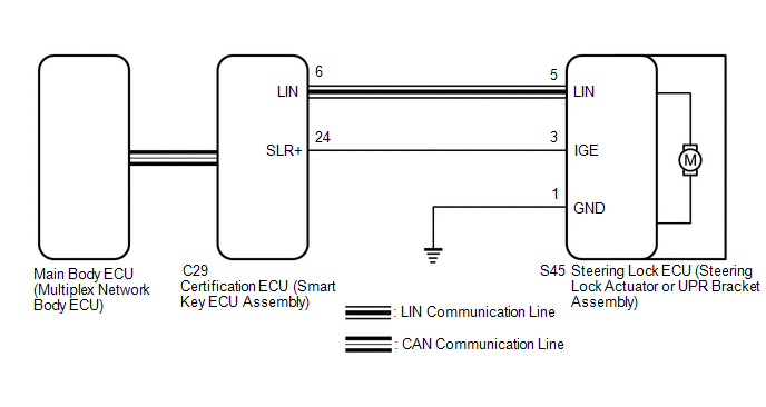
WIRING DIAGRAM
CAUTION / NOTICE / HINT
NOTICE:
- When using the Techstream with the engine switch off, connect the Techstream to the vehicle and turn a courtesy light switch on and off at intervals of 1.5 seconds or less until communication between the Techstream and the vehicle begins. Then select the vehicle type under manual mode and enter the following menus: Body Electrical / Smart Key. While using the Techstream, periodically turn a courtesy light switch on and off at intervals of 1.5 seconds or less to maintain communication between the Techstream and the vehicle.
- Perform either of the following operations to lock/unlock the steering:
- To unlock the steering, carry the key and turn the engine switch on (ACC) or on (IG).
- To lock the steering, turn the engine switch off with the shift lever in P, and then open a door.
- Make sure that no DTCs are output. If any DTCs are output, proceed to
the Diagnostic Trouble Code Chart (See page
.gif) ).
). - The steering lock system uses LIN communication. First perform the inspections
in "How to Proceed with Troubleshooting" to confirm that there are no communication
malfunctions before proceeding with troubleshooting (See page
).
- When replacing the steering lock ECU (steering lock actuator or UPR
bracket assembly) or certification ECU (smart key ECU assembly), registration
must be performed (See page ).
- After performing repairs, confirm that the problem does not recur.
- Inspect the fuses for circuits related to this system before performing the following procedure.
- When disconnecting the cable from the negative (-) battery terminal,
some systems need to be initialized after the cable is reconnected (See
page ).
PROCEDURE
|
1. |
READ VALUE USING TECHSTREAM (LOCK REQUEST RECEIVE) |
(a) Use the Data List to check if the steering lock command is functioning properly.
Smart Key|
Tester Display |
Measurement Item/Range |
Normal Condition |
Diagnostic Note |
|---|---|---|---|
|
Lock Request Receive |
Reception state of steering lock request signal by certification ECU (smart key ECU assembly) / OK or NG HINT:
|
OK: Within 10 seconds of opening any door with engine switch off and shift lever in P NG: Except above |
If this item does not change to "OK" even though the steering lock conditions are met, the certification ECU (smart key ECU assembly) may be malfunctioning. |
OK:
The certification ECU (smart key ECU assembly) receives a lock request signal within 10 seconds of turning the engine switch from on (IG) to on (ACC) or off and opening a door with the shift lever in P, and OK is displayed on the Techstream screen.
| NG | .gif) |
GO TO STEP 8 |
|
.gif)
|
2. |
READ VALUE USING TECHSTREAM (L CODE CHECK) |
(a) Use the Data List to check if L code certification is functioning properly.
Smart Key|
Tester Display |
Measurement Item/Range |
Normal Condition |
Diagnostic Note |
|---|---|---|---|
|
L Code Check |
Verification result between certification ECU (smart key ECU assembly) and steering lock ECU (steering lock actuator or UPR bracket assembly) / OK or NG |
OK: Verification result normal NG: Verification result abnormal |
When a malfunction is present:
|
OK:
OK is displayed on the Techstream.
HINT:
Reasons for verification failure:
- The steering lock ECU (steering lock actuator or UPR bracket assembly) or certification ECU (smart key ECU assembly) is malfunctioning.
- There is a problem with the communication between ECUs.
- An ECU is replaced, but is not registered.
- An ECU is replaced with an ECU which has a code already stored in it.
| NG | |
GO TO STEP 7 |
|
|
3. |
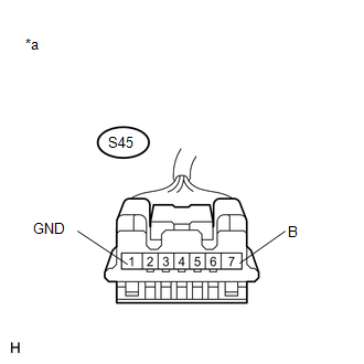
CHECK HARNESS AND CONNECTOR (POWER SOURCE TERMINAL) |
|
(a) Disconnect the steering lock ECU (steering lock actuator or UPR bracket assembly) connector. |
|
(b) Measure the resistance and voltage according to the value(s) in the table below.
Standard Resistance:
|
Tester Connection |
Condition |
Specified Condition |
|---|---|---|
|
S45-1 (GND) - Body ground |
Always |
Below 1 Ω |
NOTICE:
If the result is not as specified, check for looseness in the ground cable connection.
Standard Voltage:
|
Tester Connection |
Condition |
Specified Condition |
|---|---|---|
|
S45-7 (B) - Body ground |
Always |
11 to 14 V |
|
*a |
Front view of wire harness connector (to Steering Lock ECU (steering lock actuator or UPR bracket assembly)) |
| NG | |
REPAIR OR REPLACE HARNESS OR CONNECTOR |
|
|
4. |
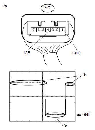
INSPECT STEERING LOCK ECU (STEERING LOCK ACTUATOR OR UPR BRACKET ASSEMBLY) |
(a) Reconnect the steering lock ECU (steering lock actuator or UPR bracket assembly) connector.
|
(b) Check the signal waveform according to the condition(s) in the table below. Standard Frequency
HINT:
|
|
| OK | |
REPLACE STEERING LOCK ECU (STEERING LOCK ACTUATOR OR UPR BRACKET ASSEMBLY) |
|
|
5. |
CHECK HARNESS AND CONNECTOR (STEERING LOCK ECU (STEERING LOCK ACTUATOR ASSEMBLY) - CERTIFICATION ECU (SMART KEY ECU ASSEMBLY)) |
(a) Make sure that there is no looseness at the locking part and the connecting part of the connectors.
(b) Disconnect the S45 steering lock ECU (steering lock actuator or UPR bracket assembly) connector.
(c) Disconnect the C29 certification ECU (smart key ECU assembly) connector.
(d) Check for deformation and corrosion of the connector case and terminals.
OK:
There is no deformation or corrosion of the connector case or terminals.
(e) Measure the resistance according to the value(s) in the table below.
Standard Resistance:
|
Tester Connection |
Condition |
Specified Condition |
|---|---|---|
|
S45-3 (IGE) - C29-24 (SLR+) |
Always |
Below 1 Ω |
|
S45-3 (IGE) or C29-24 (SLR+) - Body ground |
Always |
10 kΩ or higher |
| NG | |
REPAIR OR REPLACE HARNESS OR CONNECTOR |
|
|
6. |
INSPECT STEERING LOCK ECU (STEERING LOCK ACTUATOR OR UPR BRACKET ASSEMBLY) |
(a) Reconnect the S45 steering lock ECU (steering lock actuator or UPR bracket assembly) connector.
|
(b) Reconnect the C29 certification ECU (smart key ECU assembly) connector. |
|
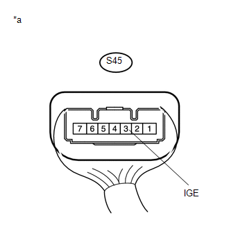
(c) Measure the voltage according to the value(s) in the table below.
Standard Voltage:
|
Tester Connection |
Condition |
Specified Condition |
|---|---|---|
|
S45-3 (IGE) - Body ground |
Always |
11 to 14 V |
|
*a |
Component with harness connected (Steering Lock ECU (Steering Lock Actuator or UPR Bracket Assembly)) |
| OK | |
REPLACE CERTIFICATION ECU (SMART KEY ECU ASSEMBLY) |
| NG | |
REPLACE STEERING LOCK ECU (STEERING LOCK ACTUATOR OR UPR BRACKET ASSEMBLY) |
|
7. |
REPLACE STEERING LOCK ECU (STEERING LOCK ACTUATOR OR UPR BRACKET ASSEMBLY) |
(a) Replace the steering lock ECU (steering lock actuator or UPR bracket assembly)
with a new one (See page ).
(b) Perform registration (See page ).
(c) Use the Data List to check if L code certification is functioning properly.
Smart Key|
Tester Display |
Measurement Item/Range |
Normal Condition |
Diagnostic Note |
|---|---|---|---|
|
L Code Check |
Verification result between certification ECU (smart key ECU assembly) and steering lock ECU (steering lock actuator or UPR bracket assembly) / OK or NG |
OK: Verification result normal NG: Verification result abnormal |
When a malfunction is present:
|
OK:
OK is displayed on the Techstream.
| OK | |
END |
| NG | |
REPLACE CERTIFICATION ECU (SMART KEY ECU ASSEMBLY) |
|
8. |
READ VALUE USING TECHSTREAM (DOOR COURTESY SW) |
(a) Using the Techstream, check the following main body ECU (multiplex network body ECU) Data List item by opening and closing the driver door to confirm the state of the front door courtesy light switch assembly.
Main Body|
Tester Display |
Measurement Item/Range |
Normal Condition |
Diagnostic Note |
|---|---|---|---|
|
FL Door Courtesy SW |
Front door courtesy light switch assembly LH / ON or OFF |
ON: Front door LH open OFF: Front door LH closed |
If this item does not change according to the actual state of the driver door, there is a malfunction in the door courtesy light switch or related part. |
OK:
The Data List item changes in accordance with the opening and closing of the driver door.
| NG | |
GO TO LIGHTING SYSTEM (FRONT DOOR COURTESY SWITCH CIRCUIT) |
|
|
9. |
READ VALUE USING TECHSTREAM (SHIFT P SIGNAL) |
(a) Move the shift lever to P.
(b) Read the Data List according to the display on the Techstream.
Power Source Control|
Tester Display |
Measurement Item/Range |
Normal Condition |
Diagnostic Note |
|---|---|---|---|
|
Shift P Signal |
Shift position (P) signal / ON or OFF |
ON: Shift lever in P OFF: Shift lever not in P |
|
OK:
ON is displayed on the Techstream.
| NG | |
GO TO ENTRY AND START SYSTEM (for Start Function) (PROBLEM SYMPTOMS TABLE) |
|
|
10. |
READ VALUE USING TECHSTREAM (STEERING LOCK) |
(a) Check that the steering is unlocked.
(b) Read the Data List according to the display on the Techstream.
Smart Key|
Tester Display |
Measurement Item/Range |
Normal Condition |
Diagnostic Note |
|---|---|---|---|
|
Steering Lock |
State of whether steering lock ECU (steering lock actuator or UPR bracket assembly) determined steering is locked / Set or Unset |
Set: Steering locked Unset: Steering unlocked |
If this item displays "Unset", the steering is not locked. |
OK:
Set is displayed on the Techstream.
| NG | |
REPLACE STEERING LOCK ECU (STEERING LOCK ACTUATOR OR UPR BRACKET ASSEMBLY) |
|
|
11. |
READ VALUE USING TECHSTREAM (LOCK REQUEST RECEIVE) |
(a) Replace the certification ECU (smart key ECU assembly) with a new one.
(b) Perform registration (See page ).
(c) Turn the engine switch on (IG).
(d) Use the Data List to check if the steering lock command is functioning properly.
Smart Key|
Tester Display |
Measurement Item/Range |
Normal Condition |
Diagnostic Note |
|---|---|---|---|
|
Lock Request Receive |
Reception state of steering lock request signal by certification ECU (smart key ECU assembly) / OK or NG HINT:
|
OK: Lock request received within 10 seconds of opening any door with engine switch off and shift lever in P NG: Except above |
If this item does not change to "OK" even though the steering lock conditions are met, the certification ECU (smart key ECU assembly) may be malfunctioning. |
OK:
The certification ECU (smart key ECU assembly) receives a lock request signal within 10 seconds of turning the engine switch from on (IG) to on (ACC) or off and opening a door with the shift lever in P, and OK is displayed on the Techstream screen.
| OK | |
END |
| NG | |
REPLACE CERTIFICATION ECU (SMART KEY ECU ASSEMBLY) |
 IG2 Signal Malfunction (B2788)
DESCRIPTION
This DTC is stored when the steering lock ECU (steering lock actuator or UPR
bracket assembly) detects an IG2 power supply malfunction.
HINT:
The steering lock ECU (steering lock actu ...
 Unable to Unlock Steering Wheel (Engine cannot Start)
DESCRIPTION
The steering lock actuator assembly activates the steering lock motor and moves
the lock bar into the steering column to lock the steering.
The steering may not unlock when the lock ba ...
Other materials:
Transfer Case Front Oil Seal
Components
COMPONENTS
ILLUSTRATION
Replacement
REPLACEMENT
PROCEDURE
1. DRAIN TRANSFER OIL
2. SUPPORT TRANSMISSION ASSEMBLY
3. REMOVE NO. 3 FRAME CROSSMEMBER SUB-ASSEMBLY
4. REMOVE TRANSFER CASE LOWER PROTECTOR
5. REMOVE FRONT PROPELLER SHAFT ASSEMBLY
(See page )
6. ...
Terminals Of Ecu
TERMINALS OF ECU
1. CHECK DRIVER SIDE JUNCTION BLOCK AND MAIN BODY ECU (MULTIPLEX NETWORK BODY
ECU)
(a) Disconnect the MB main body ECU (multiplex network body ECU) connectors.
(b) Measure the voltage and resistance according to the value(s) in the table
below.
HINT:
Measure the values on ...
Inspection
INSPECTION
PROCEDURE
1. INSPECT TIE ROD END SUB-ASSEMBLY
(a) Flip the ball joint stud back and forth 5 times as shown in the illustration
before installing the nut.
(b) Using a torque wrench, turn the nut continuously at a rate of 2 to 4 seconds
per turn and check the torque reading on the ...
