Toyota Tacoma (2015-2018) Service Manual: Transfer Case Front Oil Seal
Components
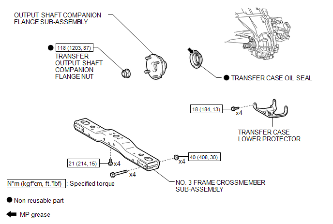
COMPONENTS
ILLUSTRATION
Replacement
REPLACEMENT
PROCEDURE
1. DRAIN TRANSFER OIL
.gif)
2. SUPPORT TRANSMISSION ASSEMBLY
3. REMOVE NO. 3 FRAME CROSSMEMBER SUB-ASSEMBLY
4. REMOVE TRANSFER CASE LOWER PROTECTOR
5. REMOVE FRONT PROPELLER SHAFT ASSEMBLY
(See page )
6. REMOVE OUTPUT SHAFT COMPANION FLANGE SUB-ASSEMBLY
7. REMOVE TRANSFER CASE OIL SEAL
|
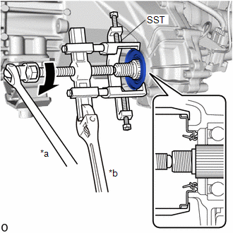
(a) Using SST, remove the transfer case oil seal. SST: 09950-40011 09951-04020 09952-04010 09953-04030 09954-04010 09955-04031 09957-04010 09958-04011 Text in Illustration
NOTICE: Apply a lubricant to the threads and end of SST. |
|
8. INSTALL TRANSFER CASE OIL SEAL
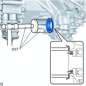
(a) Coat the lip of a new transfer case oil seal with MP grease.
|
(b) Using SST and a hammer, install the transfer case oil seal until its metal ring contacts the case. SST: 09710-30041 09710-03221 SST: 09950-60010 09951-00600 09951-00650 09952-06010 SST: 09950-70010 09951-07150 |
|
9. INSTALL OUTPUT SHAFT COMPANION FLANGE SUB-ASSEMBLY
10. INSTALL FRONT PROPELLER SHAFT ASSEMBLY
(See page )
11. INSTALL TRANSFER CASE LOWER PROTECTOR
12. INSTALL NO. 3 FRAME CROSSMEMBER SUB-ASSEMBLY
13. ADD TRANSFER OIL
14. INSPECT FOR TRANSFER OIL LEAK
 Installation
INSTALLATION
CAUTION / NOTICE / HINT
CAUTION:
Be sure to perform this procedure with several people as the transfer assembly
is very heavy.
PROCEDURE
1. INSTALL TRANSFER CASE LOWER PROTECTOR
( ...
 Transfer Case Rear Oil Seal
Components
COMPONENTS
ILLUSTRATION
Replacement
REPLACEMENT
PROCEDURE
1. DRAIN TRANSFER OIL
2. REMOVE PROPELLER WITH CENTER BEARING SHAFT ASSEMBLY
(See page )
3. REMOVE OUTPUT SHAFT ...
Other materials:
Removal
REMOVAL
PROCEDURE
1. REMOVE FUEL DELIVERY PIPE ASSEMBLY LH (FUEL PRESSURE SENSOR)
(See page )
NOTICE:
Do not remove the fuel pressure sensor from the fuel delivery pipe sub-assembly
LH.
If a fuel pressure sensor is removed, replace the fuel delivery pipe
sub-assembly LH (fu ...
Lost Communication with Meter (B1324)
DESCRIPTION
This DTC is stored when a communication error occurs between the radio and display
receiver assembly and combination meter assembly.
DTC No.
DTC Detection Condition
Trouble Area
B1324
After the radio and display receiver as ...
Reassembly
REASSEMBLY
PROCEDURE
1. INSTALL COMPRESSOR PICK UP SENSOR
(a) Install the compressor pick up sensor with the 3 screws.
(b) Engage the clamp.
2. INSTALL MAGNET CLUTCH ASSEMBLY
(a) Secure the cooler compressor assembly in a vise between ...
